| Model Railway Constructor | April 1967 |
PROTOFOUR---4 A new scale modelling standard by a model standards study group |
J. S. Brook Smith |
 The Protofour series has so far been largely theoretical in content, covering the reasons why new standards were considered necessary, the determination of the standards themselves, the characteristics of wheels and track and thoughts on wheelbase and radii. Even now, when we are approaching the construction of track, some time will have to be given to track theory.
It is the intention of the scale model railway constructor to reproduce the prototype railway scene in as faithful a manner as possible, in the hope that the resulting model will be as reliable as it is convincing in appearance. The key to convincing appearance is proportion.
Proportions
We are accustomed in the model railway world to purchase track commercially and to accept the resulting product as the best that can be produced for the purpose. Commercial tracks are designed to withstand severe mishandling and are thus more robustly built than is necessary for normal running. The rail especially is oversized, and often the track base is a plastic web which gives continuous support to the rail. These alterations to the original fine proportions of the track render most commercial products useless for scale modelling. Unfortunately track is the most obvious feature of any layout, and the visual and photographic background that justifies the proportions of the models themselves. If the track is not to scale, then the models themselves can never look fully convincing. Given correctly proportioned track, even mediocre models can be made to look the part. Therefore, dimensional accuracy of the track is of prime importance in scale modelling.
The dimensions of typical British Bullhead permanent way are given in Table 1. By adhering to these dimensions in our scale modelling we can be certain that our track will have a correct appearance.
Texture of Materials
From the dimensional table it will be seen that sleepers are generally made of wood, and they are treated with creosote to render them resistant to weathering and to insect and fungus damage. The surface texture of a creosoted sleeper cannot be reproduced satisfactorily in a material other than wood. Plastic, copper coated paxolin, fibre, and card, all have certain advantages in construction. but it is the texture which is seen and which cannot be disguised. Wood is therefore the ideal medium for sleepers in model form.
Rail and chairs. being rolled steel and cast iron respectively, soon acquire a coating of rust, grime and oil which can be represented by a coat of matt paint.
Ballast has a texture all its own, and it is rather difficult to find a suitable medium in the shops. Usually the grains are too large. or the wrong shape (maw seed or cork), or they are mixed with adhesive, which turns to a porridge on application. Ballast is also a difficult medium on account of its colour, which has to be convincing, though there may be considerable variation in the prototype.
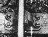 A GCR chair for plain line.
Note that there are two chair screws and two spikes in treenails. Other companies used four, three and two chair screws.
The general dimension of the chair did not vary greatly.
Colour
The question of colour is as important to the scale modeller as that of texture, and to a certain extent the two are complementary. Colour is a difficult subject to discuss, as so many individuals vary in their perception and interpretation of colours. Rather than attempt to define colour, reference is made to commercial brick papers: here we have incorrect texture as the printing ink on the paper gives an incorrect representation of the surface of a brick, and often incorrect colour when, for example, London Yellow bricks are portrayed as plain yellow. The elusiveness of "Midland Red" and Stroudley's "Improved Engine Green" serve to emphasise the importance of colour modelling. Colour, Texture, and Proportions must be given full consideration if a really convincing model is to be made. Any of the three offer a fascinating field of study, and amply repay the attention given to them.
Table 1. Typical British Bullhead Track - 1900 onwards.
| Description | Full Size | 4mm Scale | |
| Rail | Bullhead section 95 or 95R, 60 ft lengths |
5¾ in by 2¾ in | 1.92 mm by 0.82 mm |
| Chairs | Cast Iron | approx. 15 in by 7 in by 6½ in sleeper to rail 1¾ in |
5 by 2.3 by 2.1 mm 0.55 mm |
| Keys | Oak (later metal) | 6 in by 3½ in by 2½ in | 2 by 1.15 by 0.75 mm |
| Fishplates | Metal | 1 ft 6 in long | 6 mm |
| Sleepers | Wood | 10 in by 5 in by 8 ft 6 in pre-group 9 ft 0 in |
3.3 by 1.6 by 34 mm 36 mm |
| Ballast | Granite or Limestone | Maximum 2 in sieve | 0.6 mm |
Track Requirements
To handle the traffic of a railway system, the track must be correctly constructed and laid. The three requirements are:
- Track Gauge must be correct.
- The road must be correctly aligned.
- The level of the running rail must remain constant.
Examination of photographs of washed-out bridges and earthworks reveals that track is very flexible, and that once the support of the ballast and formation is removed, it will hang as loosely as a necklace. Thus, although the gauge is maintained by the sleepers, the alignment in the horizontal and vertical planes is entirely dependent upon the ballast and earthworks. As opposed to the toy train track, which depends for its alignment upon its inherent rigidity, scale model railway track must be adequately supported, which draws attention to the baseboard.
Baseboards
Track will tend to mould itself to the contours of whatever surface it is placed upon. This means that for model purposes the base must be absolutely level, otherwise, as with linoleum or other flexible floor coverings, the roughness and undulations will manifest themselves at the surface, i.e., at rail level, Apart from flatness, the baseboard must have the following characteristics:
- Dimensional Stability in changing temperature and humidity.
- High Strength/Weight ratio.
- Comparative ease of cutting and working.
- Low noise transmission factor.
The only material which seems to be completely satisfactory is chipboard. This is made from multiple layers of pine chippings or flakes, impregnated with synthetic adhesive and compressed into a firm, flat board of uniform thickness, It is thus superior for modelling bases to Plywood, as there is no warping tendency as a result of the wood grain; to Blockboard for the same reason and for its lighter weight; and to fibrous board for strength and stability.
There is still much to be investigated in the field of baseboard construction, and there may yet be a better material than chipboard, but it must be stressed that whatever substance is used for a base, it must be absolutely level, and remain so. If the modeller's ability or his pocket do not extend to satisfactory baseboards, much time, money and patience may be saved by avoiding scale model railways altogether. For the undeterred, ½ in. chipboard is obtainable at reasonable prices from wood stores and builders merchants and many such organisations are willing to cut the large sheets to sizes suitable for model railway track bases. The track bases should be screwed to a framework which will protect them from transport shocks and accidental damage. This may be made from stock size wood, and screwed to the base rather than the base being screwed to the frame, perhaps a better procedure for those modellers with limited facilities. The screws are an important detail, as they ensure a sound and rigid base which requires no more attention, especially as the base rapidly disappears under scenery and buildings and becomes inaccessible for major maintenance.
The finished bases should always be sectioned and portable, not only for the avoidance of upheaval when moving house, but for convenience of construction, assembly of track, wiring, cleaning, non-routine maintenance, alterations, and for transportation to exhibitions, for one of the finest recommendations for building a layout is the pleasure that it can give to others.
Underlay
It is possible to fix track directly to the baseboard, but experience and prudence both suggest otherwise, Some form of underlay is desirable, which will serve four purposes:
- To provide a smooth surface to which the track may be attached.
- To absorb noise.
- To absorb variations of expansion between track and baseboard.
- To give realistic surface texture to areas adjacent to the track.
Underlay must be chosen carefully, as too thin a material is insufficiently resilient, while too thick an underlay will be too flexible and will fail to hold the rail level when the latter expands with temperature. Polyurethane foam, for example, is useless for scale track underlay, though satisfactory for rigid units of commercial track. By far the best material is thin cork sheet. The underlay must be bonded to the base, and the track to the underlay, for which purposes we need a suitable adhesive.
Adhesive
As with colours and textures, adhesives offer interesting fields of discovery to the modeller, Indeed, an article on the subject in the model press would be most welcome. There are many specialised uses for adhesive in a model railway, from bonding metal kit parts to securing building papers; trackwork alone requires some quantity of adhesive, which is best bought in the cans of a builders merchant rather than the tubes of the stationer, For the purpose of this article we may consider six general types of adhesive for model railway work:
| Lignite. | Brown, water-based, slow-drying, hard when set. Cheap, but unsuitable in damp locations, as they revert in the presence of water. |
| Polyvinyl Acetate (PVA). | Creamy-white, water-based synthetic compound, Acetone aroma, semi-fast drying, comparatively inexpensive, Dries semi-hard and transparent, is water resistant when set (not water-proof). |
| Contact adhesive. | Amber coloured, petroleum based compound. Stringy, semi-hard, water-proof when set. Relatively expensive, fast drying, may be thinned with 'Trike' (trichlorethylene). |
| Epoxy Resin (Araldite). | Requires mixing of resin and hardener. Suitable only for small areas, very slow curing, expensive, waterproof and extremely hard when set. |
| Cellulose. | Rather expensive, very fast drying, transparent. Model aircraft work. |
| Latex. | Not strictly an adhesive, but a suspension of rubber in benzine. Used for the mounting of art work on card. Not a permanent bond. |
Of these adhesives, the PVA is excellent for tracklaying, as it is reasonably priced. dries slowly enough for adjustment of track between laying and setting, can be seen clearly when applied, and dries to a transparent film which will not show through a layer of ballast.
Protofour Components
Now that certain important factors relating to the track have been considered, we may see how these have affected the Protofour Group's choice of materials and techniques.
Sleepers
Protofour sleepers are made of wood. The "1/32 in." resin bonded ply is a precision product made for aircraft, and subject to Ministry specifications. Its actual thickness is 0.86mm and although this is only half the depth of a scale sleeper, this may be turned to advantage, as prototype sleepers are usually ballasted to the tops, and for model operations the remaining depth is taken up by the underlay. This also saves a considerable amount of ballast and results in a more even ballast layer.
Rail
At the time of writing, there is only one rail suitable for use with Protofour standards, and this is "Kingsway" scale Bullhead Rail, No other rail should be used for scale bullhead track, though "Kingsway" rail may be used with any 4mm scale standards, It is indeed an excellent product, allowing the construction of all kinds of lineside equipment which in the prototype are made from rail section, and giving a most convincing effect.
Ballast
Protofour ballast is the real thing granite chippings sieved through a scale 2in mesh. The resulting trackbed has a realistic texture, correct grain size, a convincing colour (which should be weathered for correct appearance) and is held securely by the carpet of adhesive that retains the track itself, As the ballast is laid on the adhesive "dry" it retains its texture and does not have a film of dried PVA over the grains.
Rail fixings
This is perhaps the most difficult single problem in trackmaking. The Group has come to the conclusion that there is no direct solution to the problem, which is hardly surprising in view of the conflicting requirements:
The fixing should eventually appear as a plain, slide block or check rail chair, complete with key.
Rails must be held securely.
Rails must remain true to gauge.
Rail height must remain constant.
Rail fixing must be permanent.
Rail alignment must be adjustable at any time.
Rail fixing must remain unaffected by environment.
Resulting track must be both strong and flexible.
Assembly must be simple, speedy and accurate.
Components should be inexpensive.
In the construction of scale trackwork, it is of great importance that adjustment should be possible at all stages of development, and the failing of systems involving scale chairs is generally that they have to be mounted rigidly to the sleeper, or that they are difficult to alter once they are laid. Protofour technique therefore centres on the method of fixing, and the chair is represented by an added moulding once the fixing is completed and finally adjusted. In the attainment of all the requirements, there seems no doubt that regardless of the development of adhesives, soldering still represents by far the most satisfactory medium for bonding a rail to a fixing. But what kind of fixing?
After considering many alternatives, the best fixing the Group has been able to find is a small rivet, The rivet is specially produced, and it is so designed that the shaft will clamp flush with the base of the wooden sleeper. The rivet head is just large enough to offer a base for the rail with some latitude for adjustment, and exactly correct for the rail height above the sleeper. The rivet is factory tinned, and contains only a small amount of metal, so that heating is very rapid and the solder will "take" without difficulty. Once fitted, the rivet may only be removed by destroying the sleeper, and the strength of the track is thus the strength of the ply. This track is remarkably strong for its weight and size, and it fulfils all the requirements; in fact it more than fulfils them, in that chairs are not needed in tunnels or sidings, and the basic construction, without chair decoration, may be used whenever desired.
The rivet system is very adaptable to switch and crossing work, as individual fixings may be "spotted" wherever required. with minimum occupation of space on the timber, and optimum electrical insulation. Electrical connections may be made below the track, by soldering a thin strip to the bases of the rivets, if necessary while track is still in the jig. However, we are encroaching on further articles, and now that details of the track components have been given, the constructional techniques will be covered in Part 5 of the series.
Copyright - Model Railway Study Group, reproduced with permission.
 Part 5