How to model a M.R. lever frame in a signalbox
-
- Posts: 366
- Joined: Sun Jul 20, 2008 5:28 pm
Re: How to model a M.R. lever frame in a signalbox
Hi Keith,
The maintainence at St Albans can obviously be carried out by crawling along behind the levers....
Cheers,
Robin
The maintainence at St Albans can obviously be carried out by crawling along behind the levers....
Cheers,
Robin
Last edited by grovenor-2685 on Sun Jan 23, 2011 11:00 am, edited 1 time in total.
Reason: changed picture tag from [url] to [img]-kn
-
- Forum Team
- Posts: 3923
- Joined: Sun Jun 29, 2008 8:02 pm
Re: How to model a M.R. lever frame in a signalbox
Mmmm-- he certainly doesn't look comfortable! Fortunately the ones I got to work on did have room to get in behind the frame as seen on the pics of Settle Jc.
Unless it was really the depth of winter I would be opening the window to work from outside, but I do have a suspicion from my visit that the windows on the restored box may be rather hard to open, if indeed they can be.
Regards
Keith
Unless it was really the depth of winter I would be opening the window to work from outside, but I do have a suspicion from my visit that the windows on the restored box may be rather hard to open, if indeed they can be.
Regards
Keith
-
- Posts: 482
- Joined: Sat Jul 26, 2008 8:08 pm
Re: How to model a M.R. lever frame in a signalbox
OK, I have another question now - judging by the two photos of box interiors on this thread (one of which is admittedly my own!), I am wondering what colour the Midland/LMS/LMR painted levers in MR signalboxes that operated both a set of points and the associated facing point lock (one lever to do both functions being a particular feature of Midland signalling practice).
The levers in Settle Jct definitely look to be all black, but what has gotten me thinking is the fact that Western practice is to paint levers that operate electric points half blue and half black....
Tim M
Member of the Devon Riviera Area Group.
-
- Forum Team
- Posts: 3923
- Joined: Sun Jun 29, 2008 8:02 pm
Re: How to model a M.R. lever frame in a signalbox
The facing points in Settle at the time of the photo clearly have an independent fpl as you can see the blue lever in the locked position with the signalman's cloth hanging on it. At St Albans the facing points also had independent fpls in the condition as preserved, in the demo they make a point of explaining that they had to be pulled off in order to clear the signals. (The fpl levers are left Normal so that they don't get in the way of the visitors, most signalmen left them locked unless the facing points concerned were moved often).
I am not sure of Midland lever colours, they may well be mentioned on the Midland Society site, but in LMR days certainly an economical lock would have a blue/black lever just like a motor operated point. except the motor operated point would have half the handle cut off so the signalman would not put his weight on it by mistake.
Regards
Keith
-
- Posts: 366
- Joined: Sun Jul 20, 2008 5:28 pm
Re: How to model a M.R. lever frame in a signalbox
Tim/Keith,
I'm not an expert but I had the following helpful reply on the Rmweb blog from Alex as follows:-
I've quickly produced a list of levers and added them to my website.
http://www.alextrack.co.uk/railways/sig ... ignal_box/
I wouldn't trust the lever lead nomenclature, it's only something I jotted down and I'm a Western man at heart and struggle with Midland peculiarities. I can't believe how 'messy' the frame is, the levers are all over the place. Thank god I was born in South Devon!
A few comments that you might find interesting... None of the starting signals were "locked by the block" so they are devoid of a white band. As far as I can tell there were no electric points or signals so all the handles would be full length, levers that don't require effort to pull were cut down as a reminder. With detonator placers the chevrons pointed up for up lines and down for down lines. Levers 19, 20 and 22 worked both the point and FPL (facing point lock) so were bottom half back and top half blue.
An interesting combination could be...
29,30,37,39,42,43 (Engine from shed to say Westerleigh Yard)
24,31,32,33 (Down Train for WR)
He suggests the levers were painted black at the bottom half and blue at the top.
Regards,
Robin
Re: How to model a M.R. lever frame in a signalbox
Robin
I expect you've worked out how to get a set of coaches and its leading engine from the gloom of platforms 12 and 13 at T.M. back to Barrow Road and safely stowed away in the carriage sidings. But I confess I do not remember seeing that actually in progress at the Barrow Road end. There is also the question of the engine that pulled out the rake in front of the arrival engine. Stowing goods trains away in Midland Rd sidings must have been interesting too. Much admiring your progress (and very envious of your abilities).
Regards, Howard
-
- Posts: 366
- Joined: Sun Jul 20, 2008 5:28 pm
Re: How to model a M.R. lever frame in a signalbox
Hi Howard,
Thank you for your kind comments.
I have been helped in my research by Patrick O'Brien who has now posted his photos on Flickr. The attached photo shows 44753 on an ECS to the carriage sidings with the 11.35 1V35 from Nottingham. There was a 4F on the 'front' , the train being top and tailed out of Temple Meads, heading up Fishponds bank before the whole train is reversed back into carriage sidings after the Black 5 is removed to go on shed.
http://www.flickr.com/photos/bristolsteam/5153652123/
Regards,
Robin
-
- Posts: 482
- Joined: Sat Jul 26, 2008 8:08 pm
Re: How to model a M.R. lever frame in a signalbox
grovenor-2685 wrote:The facing points in Settle at the time of the photo clearly have an independent fpl as you can see the blue lever in the locked position with the signalman's cloth hanging on it.
Well-spotted, Keith. How embarassing, my own photo too....
Anyway, it seems from RMWeb that the BR standard colour scheme would have been the blue and black lever, black at the bottom if I recall correctly, so that is what I shall go for, seeings as my layout is set in the BR era.
Thanks to all who have commented on my query.
Tim M
Member of the Devon Riviera Area Group.
-
- Posts: 366
- Joined: Sun Jul 20, 2008 5:28 pm
Re: How to model a M.R. lever frame in a signalbox
Just finished scratch building the Block Instruments, Bells, Telephones, Repeaters etc and fixed them to the shelf along with the Signal Diagram display panel - the latter will have a photoshopped diagram added after painting. I now have a Springside kit of whitemetal parts to sell after deciding they were not suitable.
In all a very fiddly job but the results are very satisfying.
The Block Instruments are made from 2.5mm square brass section with square section plasticard inserted into the tube, whilst the bells are turned up old 'Romford crankpins'.
The Instruments to the right are for communication between Kingswood Junction and Engine Shed Sidings, whilst to the left we have St Philips & Barrow Lane boxes.
You do not have the required permissions to view the files attached to this post.
-
- Forum Team
- Posts: 3923
- Joined: Sun Jun 29, 2008 8:02 pm
Re: How to model a M.R. lever frame in a signalbox
That does look most impressive, well done.
Keith
Keith
-
- Posts: 482
- Joined: Sat Jul 26, 2008 8:08 pm
Re: How to model a M.R. lever frame in a signalbox
Having now painted my levers:
I'm debating whether to add lever plates to them, as per Settle Jct:
On the other hand, there seem to have been a number of boxes where this practice didn't take place, and the levers had no identification plates on them (referring to some of the links provided by Keith and others further up this thread).
Not sure what to do, but if not cutting up lots of very small bits of paper, card or plasticard and trying to glue them to each lever and making them all in an exact straight line is an option, then I might just go for that...
You do not have the required permissions to view the files attached to this post.
Tim M
Member of the Devon Riviera Area Group.
-
- Posts: 2870
- Joined: Tue Jul 29, 2008 4:40 pm
Re: How to model a M.R. lever frame in a signalbox
Yes, my shot of Glendon and your shot of Settle both show the plates down behind the levers - sounds like an easier route. No point in making things difficult for yourself.
Tim V
(Not all railways in Somerset went to Dorset)
-
- Forum Team
- Posts: 3923
- Joined: Sun Jun 29, 2008 8:02 pm
Re: How to model a M.R. lever frame in a signalbox
Ah, but the plate behind the lever and the plate on the front are two different things, both became white plastic only on BR era jobs, along with the nice white covers on the lever handles.
Keith
Keith
-
- Posts: 821
- Joined: Sun Jul 20, 2008 6:02 pm
Re: How to model a M.R. lever frame in a signalbox
Speaking of handles.... I've often wondered about the rag used on the handles. Is its purpose to improve the grip or to keep the metal from tarnishing or some other arcane purpose that we mere mortals are not meant to understand?
Cheers,
David
Cheers,
David
-
- Forum Team
- Posts: 3923
- Joined: Sun Jun 29, 2008 8:02 pm
Re: How to model a M.R. lever frame in a signalbox
I always understood it to be to keep all those acids from your hands putting rust marks on the handles, but then it became tradition, hence you can see the rag in the pic of Settle even though the handles are covered with Crewe work's best white plastic meant for the same purpose.
Regards
Keith
Regards
Keith
-
- Posts: 2870
- Joined: Tue Jul 29, 2008 4:40 pm
Re: How to model a M.R. lever frame in a signalbox
The rag also acts as an insulator between your hand and the cold steel.
Point taken Keith but my shot of Glendon box, which is probably nearer Midland condition than the Settle picture, does not show plates on the levers. Picture dates from circa 1978.
Tim V
(Not all railways in Somerset went to Dorset)
-
- Forum Team
- Posts: 3923
- Joined: Sun Jun 29, 2008 8:02 pm
Re: How to model a M.R. lever frame in a signalbox
Have a look more carefully, you can see nice shiny plates on the front of the working levers, not the spares. Although that is not to say that they always had them
The plates on the lockingtray at the back usually gave the description of the item worked by that lever, Up home, Shunt to siding etc.
the plates on the lever front (pull plates) showed the lever number and listed the levers that had to be pulled first to release the lever concerned, if any. Before the BR white plastic they were usually brass.
Regards
Keith
-
- Posts: 482
- Joined: Sat Jul 26, 2008 8:08 pm
Re: How to model a M.R. lever frame in a signalbox
I'm now persuaded that the levers would have had brass plates on them, and that there would also have been brass plates on the back of the frame, as per the photos of Settle Jct and elsewhere.
Question now for me is how to replicate these? I don't want to give the impression of BR era plastic plates.
Alternatively, given that the front of the levers face away from the windows, the small size of the MR-pattern lever plates would hardly be visible - so is it worth it?
The plates on the back of the frame were larger and more obvious, again, any suggestions on how to replicate these to scale thickness with a brass finish would be gratefully received!
Tim M
Member of the Devon Riviera Area Group.
-
- Forum Team
- Posts: 3923
- Joined: Sun Jun 29, 2008 8:02 pm
Re: How to model a M.R. lever frame in a signalbox
I would think this is a case for a Jim Whittaker style punch, and get busy with a hammer and some shim brass.
An alternative could be gold coloured sticky tape or sheet, or those little self adhesive labels sold in the stationers.
Since the levers are at 6" spacing the plates must be less than 6" wide, probably around 4.5" x 8". You can probably manage wthout the engraved wording
Regards
Keith
An alternative could be gold coloured sticky tape or sheet, or those little self adhesive labels sold in the stationers.
Since the levers are at 6" spacing the plates must be less than 6" wide, probably around 4.5" x 8". You can probably manage wthout the engraved wording
Regards
Keith
-
- Posts: 482
- Joined: Sat Jul 26, 2008 8:08 pm
Re: How to model a M.R. lever frame in a signalbox
I'd say that the lever plates are around 2" wide, certainly less than 3".
I'm tempted to try making some from Eileen's 0.75mm brass strip....(epoxied on)...
I like the idea of the self-adhesive labels for the plates behind the levers, mind!
I'm tempted to try making some from Eileen's 0.75mm brass strip....(epoxied on)...
I like the idea of the self-adhesive labels for the plates behind the levers, mind!
Tim M
Member of the Devon Riviera Area Group.
-
- Forum Team
- Posts: 3923
- Joined: Sun Jun 29, 2008 8:02 pm
Re: How to model a M.R. lever frame in a signalbox
Lever plates, I'd think even less than 2". I was on about the plates at the rear, which I thought were the ones you asked about.
A few lever plates visible here but they seem to be lacking any back plates.
Regards
Keith
A few lever plates visible here but they seem to be lacking any back plates.
Regards
Keith
-
- Posts: 482
- Joined: Sat Jul 26, 2008 8:08 pm
Re: How to model a M.R. lever frame in a signalbox
Nice photo Keith - what's the location please?
I happened to visit one of our local (ex-GW) boxes over the weekend, and noticed that their lever plates were less than 2" as well, so thin, in fact, as to be almost unnoticeable when fixed within the interior of the box.... hmm, not sure what to do now - could thin some Eileens strip down further, I suppose...
Interesting that your most recent photo didn't have any rear plates behind the levers - perhaps they didn't all have these?
Tim M
Member of the Devon Riviera Area Group.
-
- Forum Team
- Posts: 3923
- Joined: Sun Jun 29, 2008 8:02 pm
Re: How to model a M.R. lever frame in a signalbox
Its St Albans South as preserved, it was in a bad way when taken over and they have only been able to replace piecemeal, so I would not deduce rfom this that it did not have rear description plates at one time, equally I don't know if they were always fitted.
more on St Albans here. http://www.tlr.ltd.uk/sigbox/home.eb
Its worth a visit if you can combine it with the CMRA exhibition, they usually open on the exhibition weekend.
interestingly, on this more recent pic BR plastic labels have been added.
Regards
Keith
more on St Albans here. http://www.tlr.ltd.uk/sigbox/home.eb
Its worth a visit if you can combine it with the CMRA exhibition, they usually open on the exhibition weekend.
interestingly, on this more recent pic BR plastic labels have been added.
Regards
Keith
-
- Posts: 482
- Joined: Sat Jul 26, 2008 8:08 pm
Re: How to model a M.R. lever frame in a signalbox
The signalbox is almost completed now. I've still to add the drain downpipe and undertake a little weathering of the structure, but here are a couple of views of it temporarily placed on the layout today:
Also a view of the interior taken outside in better light:
You do not have the required permissions to view the files attached to this post.
Tim M
Member of the Devon Riviera Area Group.
-
- Forum Team
- Posts: 3923
- Joined: Sun Jun 29, 2008 8:02 pm
Re: How to model a M.R. lever frame in a signalbox
and looking very good there Tim.
Keith
Keith
Who is online
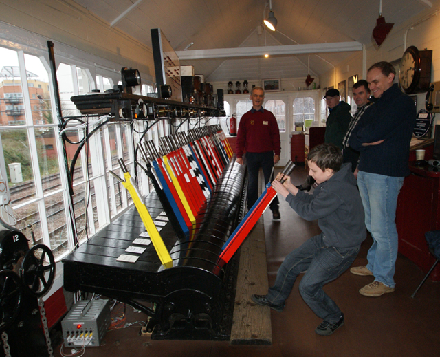
Users browsing this forum: No registered users and 0 guests