Robin,
I could bring it to show work in progress, but it's not currently operable.
Dave.
Brassmasters Blk5 45232
-
barrowroad

- Posts: 366
- Joined: Sun Jul 20, 2008 5:28 pm
Re: Brassmasters Blk5 45232
Dave, It would be good to have a look at it in the flesh - I'll leave the decision to you though:-)
Robin
Robin
-
Dave Holt
- Posts: 555
- Joined: Thu May 28, 2009 9:44 pm
Re: Brassmasters Blk5 45232
The cab doors, fall plates, handrails and intermediate buffing block have now been fitted, so the cab end of the footplate unit is complete, except for glazing and the roof. These latter will be fitted after painting.
Oil pots along each side and various bits at the front end to finish this unit off.
Dave.
Oil pots along each side and various bits at the front end to finish this unit off.
Dave.
You do not have the required permissions to view the files attached to this post.
-
Julian Roberts

- Posts: 1394
- Joined: Sat Jan 09, 2010 11:33 pm
Re: Brassmasters Blk5 45232
Dave Holt wrote: Although guided by the pipe and rod diagram for the full size loco....
Dave all the extra detail is one of the things that lifts your models to such distinction. Are pipe and rod diagrams of other steam locos generally obtainable for modellers? I'm wondering how I can get such knowledge of the detail in the case of loco kits with relatively basic instructions, DJH for example. I bought the Wild Swan book in the case of my current project but some of the drawings show more than I need to know and in doing so obscure some details I do need. A few pages of pipe and rod drawings and the photos were all I absolutely needed. Do the Brassmasters instructions show all the details you are doing? - I imagine not, in which case even a sophisticated kit like this needs additional prototype knowledge.
Thank you for continuing your inspirational thread.
-
Dave Holt
- Posts: 555
- Joined: Thu May 28, 2009 9:44 pm
Re: Brassmasters Blk5 45232
Julian, thanks for the kind comments.
As you say, the instructions in most kits are very basic and sparse when it comes to pipework, sadly including the Brassmasters ones - an exception being Dave Bradwell's 9F instructions.
I rely heavily on the Pipe & Rod and GA drawings in the Wild Swan profile books for the classes they cover. In the past, I've also bought such drawings from the old Oxford Publishing and, more recently, from the NRM. Mind you, it takes ages combing the drawing lists to find the relevant drawings and copies (electronic) are not cheap. Close-up photos in books or taken at preserved railways can also be of great help, although one has to be wary of preserved locos as they are not always done strictly to the original prototype (different injectors, requiring altered pipework routing is a common issue, especially on Bulleid pacifics).
Regarding interpretation of pipe & rod drawings, there's no getting away from the fact that they appear complicated and some vital detail being omitted or obscured. Careful study of the different views or the GA can sometimes help. Despite my professional engineering background and work on full sized preserved locos, I still struggle to work out what's what, sometimes. So you're not alone! Otherwise it's down to guesswork, but not many people will know!
Dave.
-
BryanJohnson

- Posts: 181
- Joined: Wed Jul 23, 2008 7:45 pm
Re: Brassmasters Blk5 45232
I've been using the drawings in the Wild Swan books for some of the pipework on a Jinty. I've struggled with converting the drawing's pipe specification into the external diameter to give the best size of wire to use on the model.
For example, the steam pipes controlling the delivery of sand are shown as 3/8" bore 10 IWG. Others include Injector delivery 1 1/2" bore 11 IWG and internal steam pipe 4" bore 6 IWG. All references I can find to IWG give dimensions for International Wire Gauge, and are just for wire, not pipes.
On the drawings, does IWG refer to the pipe wall thickness, and if so are there a set of values that can be used to calculate the external diameters that we need for modelling?
-
davebradwell
- Posts: 1180
- Joined: Fri Jan 18, 2019 3:48 pm
Re: Brassmasters Blk5 45232
I'll be one of many here: I think your IWG is Imperial wire gauge and my Machinery Handbook of 1959 (a great find in a charity shop) says that the British SWG was formerly called IWG. In the next paragraph it says SWG is used to specify the wall thickness of tubing.
Delving into Fowler's Mechanical Engineers Pocket book of 1919 there is a table of weights per foot of copper tubes which gives internal diameter in inches and wall thickness in IWG. This all suggests you'll be safe to work out your pipe sizes from bore and modern SWG sizes.
DaveB
Delving into Fowler's Mechanical Engineers Pocket book of 1919 there is a table of weights per foot of copper tubes which gives internal diameter in inches and wall thickness in IWG. This all suggests you'll be safe to work out your pipe sizes from bore and modern SWG sizes.
DaveB
-
Noel

- Posts: 1981
- Joined: Wed Jun 23, 2010 1:04 pm
Re: Brassmasters Blk5 45232
In my library I have a book by David Andrews about Churchward 2-6-0s. It includes two photographs of cab interiors, of 4366 in 1920 and 7320 in 1925. Both are credited to British Railways, so are presumably works official ones. The pipe runs have significant differences, as does the finish of the pipework. [The reversing lever is positioned differently and the firebox doors are different as well.] There is also a drawing of the cab interior of a screw reverser fitted Collett 93XX of 1932 as well, also credited to BR. The pipe runs shown are different to those in both photographs. Nominally all three have the same type of boiler, GW no. 4.
Boiler designs were improved over time, other equipment was added, altered or removed as well. Works drawings of pipe runs are likely to be what was started with, assuming that the shop floor didn't just decide to alter things to make its life easier, but I would question whether they were updated with changes, especially since these might be carried out in the course of overhaul or reboilering at a different works to that which built the loco, or even repairs at a running shed.
Boiler designs were improved over time, other equipment was added, altered or removed as well. Works drawings of pipe runs are likely to be what was started with, assuming that the shop floor didn't just decide to alter things to make its life easier, but I would question whether they were updated with changes, especially since these might be carried out in the course of overhaul or reboilering at a different works to that which built the loco, or even repairs at a running shed.
Regards
Noel
Noel
-
BryanJohnson
- Posts: 181
- Joined: Wed Jul 23, 2008 7:45 pm
Re: Brassmasters Blk5 45232
Dave,
Thanks for the clarification. A quick search came up with a suitable conversion chart.
I can now calculate the OD of the steam pipes controlling the delivery of sand (3/8" bore 10 IWG) as: 0.128" + 0.375" + 0.128" = 0.631".
Elsewhere on the drawing, the pipe is held with 5/8" clips, which at 0.625" is close enough to 0.631" to give me confidence that this is correct.
In 4mm scale, the closest is SWG 35 wire, so my use of the slightly thinner SWG 36 with paint should be just right. I'm also satisfied that there is the correct relationship to the diameter of the actual sand pipe.
The comprehensive conversion sheets from MRJ a long time ago include the SWG dimensions, so I now understand that these cover both wire diameter and pipe wall thickness.
Thanks again,
Bryan
-
Dave Holt
- Posts: 555
- Joined: Thu May 28, 2009 9:44 pm
Re: Brassmasters Blk5 45232
I went through the pipe & rod drawings for the Black 5 and made a table of all the pipe diameters and SWG wall thicknesses listed. I have an old copy of Kempe's Engineers Year Book (a bible in engineering design offices before the internet) which includes the actual dimension for the gauges (there were other gauge systems too, such as the Birmingham one). I calculated the various outside diameters and scale equivalent. From this, I chose the best compromise, based on the brass wire diameters available from Eileen's.
Despite this, I still managed to use the wrong diameter wire for some pipes to the live steam injector!
Dave.
Despite this, I still managed to use the wrong diameter wire for some pipes to the live steam injector!
Dave.
-
Dave Holt
- Posts: 555
- Joined: Thu May 28, 2009 9:44 pm
Re: Brassmasters Blk5 45232
Phew! It's been one of those days when you feel to be battling against the odds.
Since the previous posting, I've been adding details to the footplate unit, including cast white metal oil boxes and sand box filler pipes, etched lamp irons, wire loop grab handles and cast brass vacuum and steam heat fittings. The latter has nearly driven me to distraction.
My layout (if it ever gets completed) is set in late spring/early summer, so generally I model locos with the steam heat hoses removed and just the shut off valve mounted to the buffer beam. In this case, to make handling easier, I part cut through the hose portion of the casting at the oval flange, to leave a handle, so to speak.
After attaching to the buffer beam I completed the cut and started to trim the rearward protrusion but, in doing so, I fatigued the etched mounting tab on the buffer beam and the whole thing came adrift. Oh well, a new mounting was made from scrap etch and soldered to the now very stubby valve portion. However, I manage to attach it to the buffer beam but discovered it wasn't in quite the right position and did not align with the feed pipe, which is part of the chassis.
The valve and bracket were removed from the buffer beam but whilst repositioning it, it pinged from the tweezers. Hours of searching followed, involving completely clearing my work bench, to no avail. Then, thankfully, there it was. Right near the front of the tray but partially hidden under the back of my small vice. Finally, it's been successfully reattached in the right place. Time to go to lie in a darkened room!
Oil pots and sand fillers.
Vacuum hose and steam heat valve, grab handles, lamp irons and front oil pots.
Lubricators next.
Dave.
You do not have the required permissions to view the files attached to this post.
-
BryanJohnson
- Posts: 181
- Joined: Wed Jul 23, 2008 7:45 pm
Re: Brassmasters Blk5 45232
Thanks to the two Dave's for identifying the use of Wire Gauge in the loco drawings.
To help me in future builds, I've done a spreadsheet that takes the values off the drawing and identifies the prototype and 4mm scale external dimensions. From this, it shows the nearest equivalent wire sizes that are readily available, also showing the % differences. There's a second worksheet that does the 4mm part from an input prototype dimension in inches.
A copy of the spreadsheet is available for anyone who wants it at the bottom of this page: http://www.thurstastonp4.uk/downloads.htm
Regards,
Bryan
You do not have the required permissions to view the files attached to this post.
-
Dave Holt
- Posts: 555
- Joined: Thu May 28, 2009 9:44 pm
Re: Brassmasters Blk5 45232
Thanks for posting your pipe equivalent spread sheet, Bryan. Hopefully, people will find it useful in working out the best wire diameter to use for various pipes. Of course, that depends on accurate information about the pipe diameters used on the prototype, so those of us who lean towards Stanier ex-LMS locos are lucky to have the Wild Swan Profile books to provide that data.
Sad but almost inevitable news about S4North being cancelled. Not only is it one of my favourite shows for meeting friends and colleagues, but this year I was scheduled to demonstrate loco construction and was looking forward to chatting about the models with a number of you. Ah well.
Anyway, a bit more progress has been made, with some of the boiler fittings being attached. This particular loco had an interesting combination of features during the 1950's. It retained the long firebox throughout but received a smokebox that had a door without the support lug, the steam lance cock in the normal lower position but had the late type atomiser cover in the low position, normally associated with the later locos. The top feed cover was also the later "top hat" version introduced by Ivatt. All quite odd.
Dave.
You do not have the required permissions to view the files attached to this post.
-
Serjt-Dave
- Posts: 643
- Joined: Tue Oct 02, 2012 3:31 pm
Re: Brassmasters Blk5 45232
Lovely work there David, though it's making me having the urge to start my ones. But I must be strong and finish my 4f first. LOL.
Like yourself I'm gutted about S4N but it has to be.
Dave
Like yourself I'm gutted about S4N but it has to be.
Dave
-
Dave Holt
- Posts: 555
- Joined: Thu May 28, 2009 9:44 pm
Re: Brassmasters Blk5 45232
Not much progress in almost a week. However, i have been working on the vacuum ejector and its discharge pipe that runs along the side of the boiler. Inspired by some wonderful 7 mm scale modelling, I've tried to represent the gland nuts on the drain pipes on the ejector body and pipe elbow with inserts of fine tubing - 0.5 mm o/d. Fiddly to say the least. In the past. I've represented the drains with 0.2 mm tinned copper fuse wire but the real thing was only 0.375" o/d, or 0.125 mm on the model. Some 0.122 mm soft brass wire was obtained recently but it's like modelling with hair! Not sure if I'll use this or revert to the over-scale copper wire.
Exhaust pipe and ejector trial fitted to the boiler.
Close-up of the ejector with the brass tube gland nuts just visible on the bottom and the steam pipe nut at the rear. A length of the scale diameter drain pipe wire runs across the image, below the ejector casting.
Dave.
Exhaust pipe and ejector trial fitted to the boiler.
Close-up of the ejector with the brass tube gland nuts just visible on the bottom and the steam pipe nut at the rear. A length of the scale diameter drain pipe wire runs across the image, below the ejector casting.
Dave.
You do not have the required permissions to view the files attached to this post.
-
Dave Holt
- Posts: 555
- Joined: Thu May 28, 2009 9:44 pm
Re: Brassmasters Blk5 45232
Compromise! I decided to represent the drain pipes with slightly over scale 0.152 mm wire. Doesn't look too chunky to me and was easier to handle than the really fine stuff.
A little bit untidy but I can live with it. You wouldn't believe the number of goes it took to get all three legs engaged in those 0.5 mm tubes at the same time and get them secured.
Dave.
A little bit untidy but I can live with it. You wouldn't believe the number of goes it took to get all three legs engaged in those 0.5 mm tubes at the same time and get them secured.
Dave.
You do not have the required permissions to view the files attached to this post.
-
johndarch

- Posts: 162
- Joined: Tue Jan 29, 2019 11:24 am
Re: Brassmasters Blk5 45232
"You wouldn't believe the number of goes it took to get all three legs engaged in those 0.5 mm tubes at the same time and get them secured."
Oh yes I would! Keep up the good work Dave.
Oh yes I would! Keep up the good work Dave.
-
Dave Holt
- Posts: 555
- Joined: Thu May 28, 2009 9:44 pm
Re: Brassmasters Blk5 45232
Well, progress has slowed, barely credible I know. I see several fellow modellers experiencing increased modelling time due to the coronavirus lockdown. However, it's had the opposite effect on me since my partner can no longer work, resulting in us spending more time together during the week. In effect, I've lost four whole afternoons per week from my modelling time. Still she's definitely worth it.
Nevertheless, some progress has been made, with the ejector and discharge pipe and the hand rails being fixed to the boiler.
The atomiser steam pipe and ejector pipe drain have been made from 0.33 and 0.152 mm brass wire, respectively. I had a setback with the latter when I managed to snap off a 0.2 mm drill bit in the drain boss and couldn't extract the broken piece. Luckily, I managed to solder the wire to the end of the boss. An inherently weak arrangement but, with care in handling, should be OK in this relatively protected area.
The injector delivery pipes above the footplate to the lower boiler sides have been formed (0.7 mm brass rod) and temporarily plugged in place. They still require some minor tweaking to get the run along the inner footplate edge a bit better, but the hard part is done. Final fixing will be part of permanently attaching the boiler unit.
Dave.
You do not have the required permissions to view the files attached to this post.
-
Dave Holt
- Posts: 555
- Joined: Thu May 28, 2009 9:44 pm
Re: Brassmasters Blk5 45232
Lubricators and oil pipes done. I had to shorten the lubricator drive mechanism and elongate the locating holes inboard so that the drive arm, not part of the kit, aligned with the slot in the footplate and the top, rear edge of the lubricator body just cleared the boiler. The oil pipes are represented by 0.122 mm brass wire (about scale diameter), which pass through 0.5 mm o/d tubes set into the cast body to represent the gland nuts. All rather fiddly, to say the least. I'm not too sure exactly where these pipes were routed, apart from two from the axle-box lubricator, which run to the rear and disappear through two holes in the footplate. I gathered all the other pipes together behind the lubricators and bent the ends over the inside of the frames, just in front of the firebox. Thankfully, the RH injector delivery pipe clears the backs of the lubricators.
Cylinder lubricator steam heating pipe, with its shut-off cock and bracket, still to do.
Dave.
Cylinder lubricator steam heating pipe, with its shut-off cock and bracket, still to do.
Dave.
You do not have the required permissions to view the files attached to this post.
-
johndarch
- Posts: 162
- Joined: Tue Jan 29, 2019 11:24 am
Re: Brassmasters Blk5 45232
You do have remarkable patience Dave. Lovely work.
-
barrowroad
- Posts: 366
- Joined: Sun Jul 20, 2008 5:28 pm
Re: Brassmasters Blk5 45232
Stunning work Dave it look fantastic.
Robin
Robin
-
DougN
- Posts: 1253
- Joined: Wed Sep 01, 2010 9:57 am
Re: Brassmasters Blk5 45232
Really well done Dave. That is one of the tasks I am not looking forward to on my V2's I will no doubt dig out MRJ 66 and 67 to see how John Haynes managed to get them all soldered in place! Here is the only other place I have seen it done 
Doug
Still not doing enough modelling
Still not doing enough modelling
-
Dave Holt
- Posts: 555
- Joined: Thu May 28, 2009 9:44 pm
Re: Brassmasters Blk5 45232
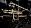
The cylinder lubricator steam heating pipe has now been made and fitted. This completes the detailing of the footplate unit, although a bit more cleaning up of excess solder might be in order.
Pipes into and out of the cylinder lubricator, made from 0.2 mm tinned copper wire. Gland nuts represented by 0.5 mm o/d tube.
The shut-off cock is an Alan Gibson flangeless handrail knob on a short length of 0.5 mm tube mounted to a small bracket made from thin N/S strip. The feed pipe is 0.33 mm brass and the outlet 0.2 mm.
And an overall view showing the pipe run along the footplate. This is deliberately not dead straight as prototype photos show it to be generally a dog's hind leg.
Adding weight to the boiler is next, I think.
Dave.
You do not have the required permissions to view the files attached to this post.
-
Julian Roberts
- Posts: 1394
- Joined: Sat Jan 09, 2010 11:33 pm
Re: Brassmasters Blk5 45232
Wow 
The idea of a tube 0.5 to represent the lubricator glands is really helpful. I'm at this stage on my Compound as a friend Andrew has very generously said he can drill the lost wax castings for me.
Do you know about this? - the Compound lubricators had 6 pipes originally each side. I see you have 3; BR days (my time period) photos show varying numbers of them (on the Compound) - as few as 2 sometimes - but no photo shows both sides of the lubricator. Do you know, in general terms, i.e. not particularly for the Compound, if there would be the same number of pipes each side (of a single lubricator)?
I have found the wire that wraps piercing saw blades is roughly about the same as your 0.122!
Showing my ignorance, do you glue metal fixings to the resin boiler, if so what glue do you use?
-
Dave Holt
- Posts: 555
- Joined: Thu May 28, 2009 9:44 pm
Re: Brassmasters Blk5 45232
Julian,
I'm not sure there's a simple answer to the question of numbers of feeds from each lubricator but I don't think you'll be too far out if you assume the same number from each side. On Black 5's, the larger, cylinder lubricator, there are 12 feeds, 6 each side - although on my model the rear side only has 5 because I broke a drill bit off and couldn't extract it. It doesn't really show, being masked by the other lubricator. Good job it wasn't on the front side!
The smaller axlebox lubricator was an 8 feed unit, but the innermost feed was blanked off on both sides - as there's only 6 axleboxes.
That said, Jubilees appear to have a 16 feed cylinder lubricator (LHS) and an 8 feed - all used - mechanical one (RHS). Scots had an even larger mechanical lubricator on the RHS. So that's my logic blown out of the water.
Regarding fixing metal fitting to the resin boiler, I used various types of superglue so far. I'm intending to use epoxy to fix the boiler to the footplate and, perhaps, the chimney and steam pipes to give a bit more adjustment time before things start to grip.
When I said the footplate detailing was complete, I had overlooked the lubricator drive rods, located just below the edge of the footplate. This omission has been rectified with some rather impressionistic representations - as seen in the photo. The real things had forked ends. I did this on my previous Black 5 but, to be honest, they looked a bit over scale so, on this model I simply flattened the ends of the brass wire used yo represent the rods and filed the resulting ends to shape. Better than nothing.
Dave.
You do not have the required permissions to view the files attached to this post.
Who is online
Users browsing this forum: No registered users and 0 guests