This follows discussions on two other threads
viewtopic.php?f=5&t=6257
viewtopic.php?f=5&t=5728&start=100
Martin Wynne wrote:p.s. Dave,
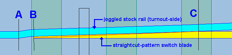
If it helps to understand what's happening in a joggle, I have added a red line to the diagram:
The red line shows the position of the stock rail for a plain set with no joggle. To make the joggle, imagine the stock rail being held along the red line, and then pushed sideways at B.
You can see that this means that when there is a joggle, there is also very slight bend in the stock rail at C. This angle is so small that it is normally ignored for construction purposes.
(For an A switch with 66" planing, and a tip of 3/8" thickness, that small angle is 1:176 = 0.3 degrees. For longer switches it is even smaller.)
If you like to use over-scale depth joggles, as many do, that angle will increase, and you might want to bear it in mind. It is more evident when there is a joggle in the straight (main-road) stock rail
Martin.
(My italics)
I want to confirm whether the drawing below (showing a RH turnout) is correct. Martin's diagram above shows the diverging (LH) stock rail, and I want to know if how I've drawn the main road straight stock rail, which I've inferred from the drawing above, is correct. The important point being that the normal track gauge of the straight stock rail is fully restored only at the stockgauge, the end of the planing length - is that right? (Obviously the amount it is overgauge is tiny so I'm talking about something almost invisible. The drawing is a huge exaggeration of what goes on simply for clarity. )
The return length and depth of the joggle are not the issue here.
If this is correct then I imagine that when laying the straight stockrail first, between the stockgauge and the end of the joggle is an area of uncertainty. If using a ruler the length between A and C will not abut the ruler.
Here is a Templot A6LH with joggled stockrails.