John Redrup gave me these codes for the cables and plugs from RS Components:
Red wire 748 1976
Black wire 748 1970
Black plug 641-8019
Red plug 641-8075
Resistance Soldering
-
Jol Wilkinson

- Posts: 1116
- Joined: Mon Jul 21, 2008 7:39 pm
Re: Resistance Soldering
Those cable references may be for PVC, however 2.5mm2 silicone sheathed is also available from RS. Search under Hook up and Equipment wire with silicone insulation.
-
David B
- Posts: 1518
- Joined: Sun Jul 20, 2008 5:30 pm
-
David Thorpe
Re: Resistance Soldering
Bit cheaper here (if it's the same sort of stuff): https://www.rapidonline.com/Unistrand-3 ... ZVEALw_wcB
-
David B
- Posts: 1518
- Joined: Sun Jul 20, 2008 5:30 pm
Re: Resistance Soldering
It's almost a year since my articles on resistance soldering were published in S4 News (206 and 207). I know a large number of units have been purchased since then, perhaps a few by Scalefour members. So how have people been getting on with their purchases?
I am making a couple of Jeremy's excellent GWR Railmotor power units, putting on rivet overlays where the RSU has been invaluable. In the past year, I have also come round to using a plate more.
First, I tinned the overlays that go round the bearings. For those making these units, filing the etch cusp in the cut-outs helps the bearings slide much better. Being dim, it took me a while to work this out!
I fluxed the chassis where the overlay was going, slid the bearing to the top and placed the overlay in position. It has not yet been soldered though it might look like it.
Holding the overlay in place with the probe, I slid the bearing out of the way and made the first zap in the middle of the overlay. A couple more zaps, working away from the middle and . . .
. . . the job was done. The overlays round the motion bracket slot are next where I will use a scalpel blade in the slot to line them up.
What have other people been doing with their resistance soldering units? Do add your contributions to the thread.
You do not have the required permissions to view the files attached to this post.
-
steve howe

- Posts: 912
- Joined: Sun Feb 01, 2009 10:16 pm
Re: Resistance Soldering
H David,
At the risk of turning it into another topic, I for one would be very interested to see how you progress the railmotor chassis. Detailed shots like this are so useful to people like me fumbling around!
Steve
At the risk of turning it into another topic, I for one would be very interested to see how you progress the railmotor chassis. Detailed shots like this are so useful to people like me fumbling around!
Steve
-
David Thorpe
Re: Resistance Soldering
I've just finished using my resistance soldering iron to fit lamp irons onto the C16 tank engine I'm in the process of finishing. It really is excellent for a job like that - tin the lamp iron, hold it in place with the probe, give it a quick blast but then keep the probe on it for a few more seconds, and there it is. Needless to say I did manage to concoct a problem - while giving the quick blast I inadvertantly allowed the top of the probe to come into contact with the handrail I'd spent the previous evening shaping to fit, and it snapped apart. However, I think I made better job of the replacement so I suppose it all ended well.
DT
DT
-
CornCrake
- Posts: 131
- Joined: Sat Dec 05, 2015 2:03 pm
Re: Resistance Soldering
Hi David,
What method did you use for pressing out the rivets in the sideframe?
What method did you use for pressing out the rivets in the sideframe?
-
David B
- Posts: 1518
- Joined: Sun Jul 20, 2008 5:30 pm
Re: Resistance Soldering
CornCrake wrote:What method did you use for pressing out the rivets in the sideframe?
On this occasion, a GW press but on an earlier one I just used an ordinary steel scribe.
-
BryanJohnson

- Posts: 181
- Joined: Wed Jul 23, 2008 7:45 pm
Re: Resistance Soldering
David asked - What have other people been doing with their resistance soldering units? Do add your contributions to the thread.
Some Rumney Models Tarpaulin Bar trapezoidal board fixing straps.
Some Rumney Models Tarpaulin Bar trapezoidal board fixing straps.
You do not have the required permissions to view the files attached to this post.
-
Bernie
- Posts: 43
- Joined: Thu Dec 28, 2017 1:40 pm
Re: Resistance Soldering
The device arrived. Crivens, I thought I enjoyed Jean Michel Jarre! Docklands all over again to start with. Sparkier, but drier.
Thankfully not Houston.
Somewhat energetic, went from no heat to shooing away itenerant witches looking for a cheapo coven. BPM over 0 being a thing to treasure, I look forward to DavidB at S4N.
Here goes,
Bernie
Thankfully not Houston.
Somewhat energetic, went from no heat to shooing away itenerant witches looking for a cheapo coven. BPM over 0 being a thing to treasure, I look forward to DavidB at S4N.
Here goes,
Bernie
-
Paul Townsend

- Posts: 964
- Joined: Mon Sep 14, 2009 6:09 pm
Re: Resistance Soldering
Answering David B's "what do you use your RSU for":
Building Broad Gauge Baulk Road track with my fancy tweezers....on display at DB's stall in Wakefield.
Building Broad Gauge Baulk Road track with my fancy tweezers....on display at DB's stall in Wakefield.
-
Bernie
- Posts: 43
- Joined: Thu Dec 28, 2017 1:40 pm
Re: Resistance Soldering
Maybe I should have said 'I quite look forward to DB's demo', as opposed to going loop de loo.
Hindsight is useful, I guess.
Apologies.
Bernie
Hindsight is useful, I guess.
Apologies.
Bernie
-
Paul Willis

- Forum Team
- Posts: 3048
- Joined: Sun Jul 20, 2008 6:00 pm
Re: Resistance Soldering
Bernie wrote:Maybe I should have said 'I quite look forward to DB's demo', as opposed to going loop de loo.
Hindsight is useful, I guess.
Apologies.
Bernie
No apologies needed here. I found it entirely comprehensible!
Cheers
Flymo
Beware of Trains - occasional modelling in progress!
www.5522models.co.uk
www.5522models.co.uk
-
Bernie
- Posts: 43
- Joined: Thu Dec 28, 2017 1:40 pm
Re: Resistance Soldering
I thought I was an outside cheeky bet for the RSU GP championship this afternoon. Come 6pm I have knocked Picasso into a cocked hat.

Oh well, tomorrow's another day.
HLKits, how many 03/04 chassis kits in stock?
Oh well, tomorrow's another day.
HLKits, how many 03/04 chassis kits in stock?
-
Bernie
- Posts: 43
- Joined: Thu Dec 28, 2017 1:40 pm
Re: Resistance Soldering
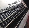
first attempt.
I think the rear steps ( on the left) would look super in a scrapheap.
I think the rear steps ( on the left) would look super in a scrapheap.
You do not have the required permissions to view the files attached to this post.
-
Paul Townsend
- Posts: 964
- Joined: Mon Sep 14, 2009 6:09 pm
Re: Resistance Soldering
Bernie wrote:first attempt.
IMG_0840.JPG
I think the rear steps ( on the left) would look super in a scrapheap.
There is nothing there that can’t be rescued.
The laminations at top left are separated and too much stray solder in several places.
I would apply heat sink clips nearby where laminations are Ok. Large solder iron to top left then while molten squidge the lams with pliers. Remove iron, hold pliers until cold. Check and repeat until happy.
Excess solder can be removed with iron and solder wick, used with lots of flux. Again use heat sink to avoid collapse.
Finish with brass bristle brush.
Steps should be well dirty so you can hide many blemishes !
-
David B
- Posts: 1518
- Joined: Sun Jul 20, 2008 5:30 pm
Re: Resistance Soldering
Paul is quite right, Bernie. There is nothing here that cannot be salvaged and he gives you good advice. Some of those bits are quite delicate so you might find you need to reduce the voltage to solder them and you will not need to keep your foot down for very long.
Use less solder! It is surprising how little you need. If you find it difficult to get small amounts on your iron, cut small pieces first. Remember that it is easier to add solder than to remove it.
However, well done - you have made a start which is more than some people have managed. Keep going and you will get the hang of using resistance soldering, though it is not a replacement for the soldering iron. You will soon pick up on which jobs are right for the different tools.
-
Bernie
- Posts: 43
- Joined: Thu Dec 28, 2017 1:40 pm
Re: Resistance Soldering
Thank you, gents, for your help. I'll have another go when I've put my bike back together. Thankfully it doesn't require any soldering!
-
junctionmad
Re: Resistance Soldering
Anyone know a source of suitable transformers that could be pressed into service for resistance soldering ?
Dave
Dave
-
Jol Wilkinson
- Posts: 1116
- Joined: Mon Jul 21, 2008 7:39 pm
Re: Resistance Soldering
junctionmad wrote:Anyone know a source of suitable transformers that could be pressed into service for resistance soldering ?
Dave
The subject of building your own RSU to save money has never, as far as I know, identified a suitable, readily available, transformer. Twenty or more years ago Maplin used to sell a 100va transformer kit on which you could wind your own secondary outputs. Getting the large diameter enamelled wire closely wound around the bobbin wasn't at all easy (I built one at the time).
Claims have been made that car battery charger transformers could be used, but I have never seen any details of one which was shown to have worked successfully.
The most successful commercial RSUs have used tapped secondary windings giving several low voltage outputs. Such transformers have usually been specially manufactured. The outputs are usually up to 5 volts and 20 amperes
The exception is the very expensive (in railway modeller's terms) American Beauty unit which has a continually variable output. Possibly based upon that, I have seen a suggestion that a low voltage lighting transformer, with the input voltage supplied by a Variac, is one possible design. However, the cost of the Variac and transformer would be in the region of £90 or more and whether the output at lower than the design voltage rating of the transformer would be sufficient I can't say.
A variac capable of giving 20A output and so obviating the need for the low voltage transformer would cost around £200 from one of the UK electronic suppliers such as Farnell. That would probably be the equivalent of the American Beauty design (although possibly with a lower output). Add the cost of a good quality footswitch and making/buying a good probe carrier/handle and it would be more expensive than the units currently sold for model making use.
Perhaps all that explains why, although an internet search will turn up several suggestions and designs for self built RSU's, few people have apparently done it.
Jol
-
junctionmad
Re: Resistance Soldering
It would be an interesting project to develop a solid state version , easy enough with some big power mosfets and a back end switching system ( well not that easy )
I looked at getting a custom toroidal traffo wound , entirely do-able but a little pricey in 1 offs
I looked at getting a custom toroidal traffo wound , entirely do-able but a little pricey in 1 offs
-
David Thorpe
Re: Resistance Soldering
Jol Wilkinson wrote:The subject of building your own RSU to save money has never, as far as I know, identified a suitable, readily available, transformer. Twenty or more years ago Maplin used to sell a 100va transformer kit on which you could wind your own secondary outputs. Getting the large diameter enamelled wire closely wound around the bobbin wasn't at all easy (I built one at the time).
I have a Swanage Models RSU and have been very pleased with it. However, I note that back in July 2018 Peter leJeune, who makes that model, was having difficulty in finding transformers for it as his supplier had retired. Whether or not he overcame that problem and his unit is back on sale I do not know. The London Road Models one seems to be on sale though when I looke it up on their website I found that no price was shown for it, so maybe it's not currently (sic) available?
DT
-
Jol Wilkinson
- Posts: 1116
- Joined: Mon Jul 21, 2008 7:39 pm
Re: Resistance Soldering
David,
the price is given in the "Gears, motors, etc., soldering materials and tools" section., £210 complete including probe, leads, etc.
The transformers for the LRM unit are manufactured by a company specialising in custom transformers, so ongoing supply of RSUs shouldn't be a problem. They are usually produced in batches, so may not always be "off the shelf"
Jol
-
David B
- Posts: 1518
- Joined: Sun Jul 20, 2008 5:30 pm
Re: Resistance Soldering
Jol refers to the probe. A new source being needed, the probe has been redesigned and I have one on my bench. The original push-fit collar has been replaced by a threaded collar which gives a more positive grip on the carbon rod. It is now less likely that the collar becomes detached and lost which I understand has happened to some people.
You do not have the required permissions to view the files attached to this post.
Return to “Tools and Techniques”
Who is online
Users browsing this forum: No registered users and 0 guests