Julian Roberts wrote:Do I understand correctly that on the switchblades, you say the horizontal profile is a straight line from the tip to the stockgauge, the full length of the planing, rising from the 0.25mm below rail level at the tip?.
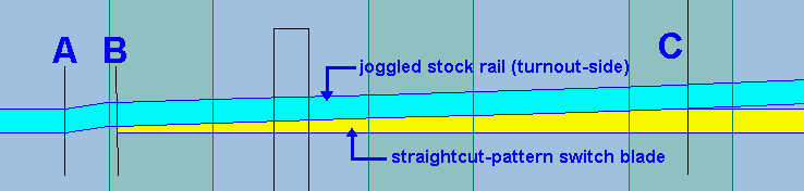
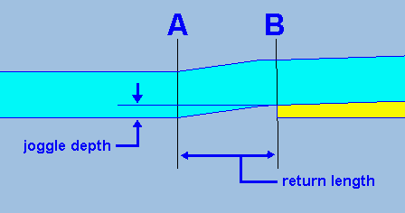
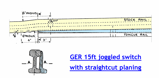
For this type of switch, which is semi-curved, Yes. The important thing is to produce an even taper over the length of the planing. (Better for it to be slightly hollow rather than convex).
My experience with switches is that if the blades are less than full height after a certain point of their length, a wheel can tend not to take the direction of the switch, particularly the diverging route. However at the tip (as you have shown) it does need to be below rail level or there will be gauge narrowing, as (surely?) it's not possible to file rail to less than about 0.2 thickness, which on a B switch will be approx 7mm from the tip - so my horizontal taper has been from there to the tip, made naturally by the filing.
I have just measured one of my switch blades at the tip with a micrometer and the rail thickness is 0.2mm, however this is at a point about half way down the rail height as there is a vertical taper to the rail above this, which is maintained for at least half the length of the planing.
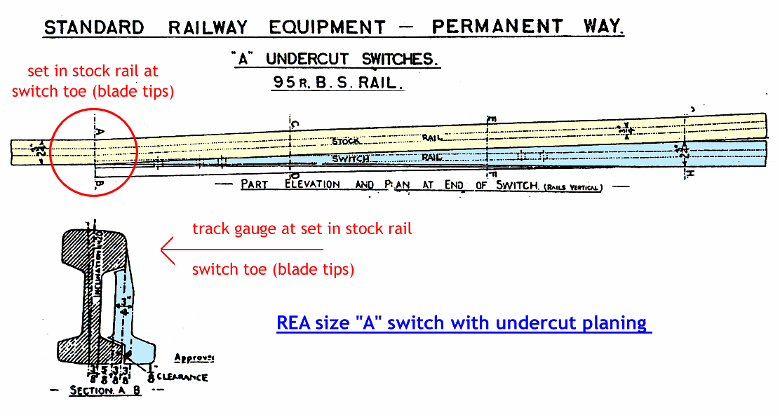
Here is a diagram of an undercut switch showing the section at the toe or tip of the blade. Obviously we cannot hope to produce such a section and the reality is that the back of our switch blades will be flat as per the vertical line down the middle of the switch blade. The important thing to note though is the chamfer to the top edge of the running face. This is pretty much the last operation described in making the switch blade.
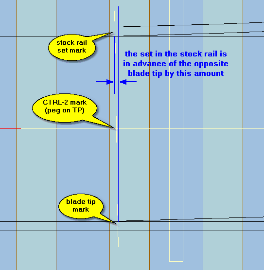
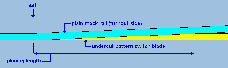
The idea of this chamfer is to deflect the flange and guide it away from the stock rail. It will continue to do this for some distance as the head of the switch blade rises until the tread of the wheel makes contact with it. The reason for the set leading the switch tip is to allow some clearance for the thickness of the switch blade as well as matching the angle of deflection.
At your half way point, say 15mm, the rail top is theoretically c.0.1mm below the stock rail if I get you right. Clearly these are almost just numbers but I would be worried about any encouragement of our P4 wheels not to take the right course.
If the head of the switch blade were flat then yes it could well pick up the flange and cause a derailment, but it isn't. (See above).
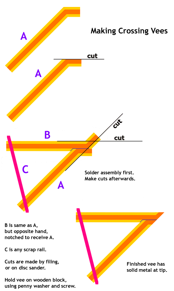
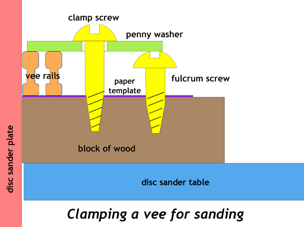
Going to the crossing, while your knuckle is directly on a timber I have seen turnouts where the knuckle is between two timbers, and this is the case on Martin Wynne's post of a Templot crossing in your Brimsdown thread.
If the knuckle is between two timbers it would be much easier to see the place where the bend should be once the timbers are stuck down onto the template.
Prototype practice varied, I take it?
Where the knuckle bend occurs depends purely on the angle of the crossing and the width of the crossing flangeway. As the angle changes, the distance from the blunt nose to the knuckle bend will change also. As the timber centres are at fixed spacings they will inevitably clash at some settings.
I must say I would be happier (with my third hand) to use a ruler to be sure to exactly align the running route of first knuckle/wing rail with the V as well as using the drawing, as (maybe it's my eyesight) I would not be sure I had the exact vertical perspective.
Having soldered the first two joints for the wing rail and checked the alignment with the rule, I was not satisfied with it, it is a simple matter to unsolder the wing rail and shift it forward or back a small amount as required and try again.
Regards
Tony.
 These notes apply to UK-pattern bullhead track only.