The chassis I am making has two side beams acting as compensators for a pair of axles (a third axle is compensated by a central knife edge). I am not interested in constructing an entirely different system of compensation, I want to build the chassis as designed. I am not clear exactly how the side beams are attached. Clearly they must be distanced from the frames so that there is a limited bearing surface rather than rubbing along their whole length (marked as spacer collar on the drawing). I am assuming the bushes are fixed in the beams and the axles go through extended holes in the frames. What might be the best way of attaching the beams so that they can rotate around the fulcrim. The drawing (not dimensioned!) below shows the general shape of the beams, plus a top view of the arrangement with the frames.
attaching a compensation beam
-
jon price
- Posts: 641
- Joined: Mon Jun 07, 2010 2:34 pm
attaching a compensation beam
You do not have the required permissions to view the files attached to this post.
Connah's Quay Workshop threads: viewforum.php?f=125
-
grovenor-2685

- Forum Team
- Posts: 3922
- Joined: Sun Jun 29, 2008 8:02 pm
Re: attaching a compensation beam
Does the rod acting as fulcrum go across the frames from side to side or does it have to be a short pin for each frame?
If the former I would suggest a small top hat bearing in each beam to give a nice bearing on the pivot rod, and a tube over the centre of the rod to stop the bearings moving inward, the brim of the hats will act as your spacer.
If the latter the top hat bearings can just sit on stubs of rod but you will need an alternative spacer, this could be done on the axles, the gearbox may do for one of them, or by a retainer fixed to the side frames or a crossmember, wherever convenient.
If space is tight I think you could omit the spacers and let the beams rub on the frames, I don't think any resultant friction would be significant.
NB If the axle bearings are soldered into the beamsthey need to allow the axle to rock within the bearings as the beam works. Alternativel leave the bearings free to rock in the beam and provide something to stop bearing rotation.
Regards
-
Jol Wilkinson

- Posts: 1114
- Joined: Mon Jul 21, 2008 7:39 pm
Re: attaching a compensation beam
Jon,
the spacer collar need only be etch thickness. Presumably the bearings are meant to be fixed in the beams.
So why not have a piece of tube to fit around the beam fulcrum wire, between the beams and long enough to hold the beams in place with a small amount of clearance. The spacer collars can be soldered to the beam to hold them in place during assembly. The fulcrum wire (1.0mm or 1/16" would be fine) can be finally fixed in place with a spot of glue where it passes through the frames, so could be removed at a later date if needed. Alternatively a small hole/slit in the centre of the tube with a spot of glue to fix it to the wire. There should be no side thrust on the fulcrum wire so not a lot of effort needed to hold it in place.
Jol
-
jon price
- Posts: 641
- Joined: Mon Jun 07, 2010 2:34 pm
Re: attaching a compensation beam
Thanks Keith and Jol. Exactly what I needed to know.
Connah's Quay Workshop threads: viewforum.php?f=125
-
John Palmer
- Posts: 825
- Joined: Fri Jul 15, 2011 11:09 pm
Re: attaching a compensation beam
Any excuse to pull out the camera!
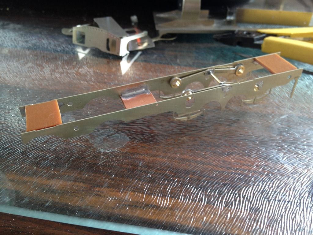
Here's a picture showing the beam arrangement for my second Johnson bogie tank 58047, completed within the last year, tho' the wheels, frames and drive were assembled about 25 years ago when compensation was more in vogue.
Hopefully the picture shows exactly the kind of arrangement you have in mind. To mount the beams I bored and tapped the mainframes 6BA and let in short lengths of studding. The beams were pivoted on top hat bushes bored to be a close fit on the studding. Once located on the studding the beams are held in place with 6BA nuts nipped up against the top hat brim. An advantage of this arrangement is that, with the nuts removed, it is, in principle, possible to slide the beams inboard clear of the studding, at which point the wheelsets can be dropped out of the frame. In practice that hasn't proved necessary. Note that Kemilway spring etches have been soldered to the outboard faces of the beams and act to space them clear of the frames. As Keith suggests, the frictional resistance that might limit rotation of the beams is negligible.
In view of the retrospective look being taken at Mike Sharman's contribution to the hobby, be it noted that this locomotive drew heavily on Mike's components: those are his wheels and 38 : 1 worm box, which I've geared down further with a 2 : 1 spur gear set to take the total reduction down to 76 : 1. And very nicely she runs too.
You do not have the required permissions to view the files attached to this post.
-
garethashenden
- Posts: 406
- Joined: Tue Apr 07, 2015 9:41 pm
Re: attaching a compensation beam
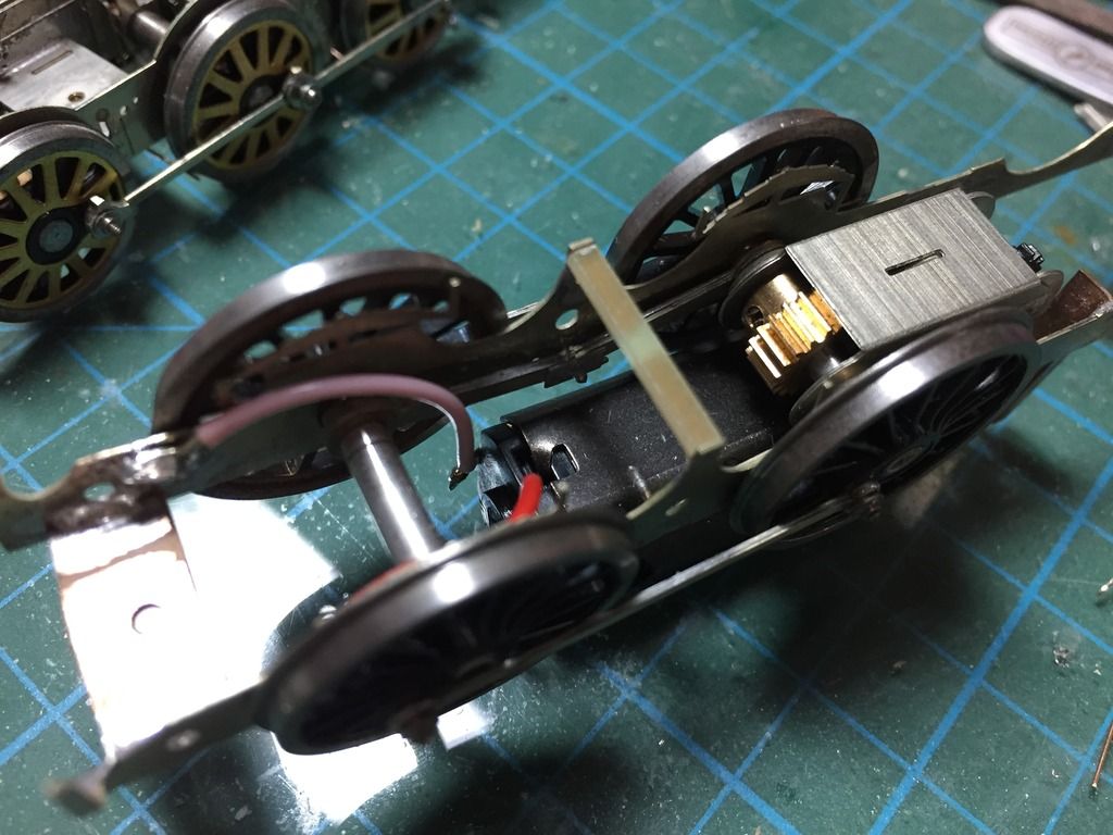
Here's how I did it on a chassis with this design. The beams are mounted on a length of wire soldered between the frames. They are then held close to the frames by scrap etch with a hole through the middle. The wire was then cut out from the middle. It's all rather messy and will be cleaned up when I get around to changing the wheels from EM to P4. The compensation works very well with this setup.
-
jon price
- Posts: 641
- Joined: Mon Jun 07, 2010 2:34 pm
Re: attaching a compensation beam
Thanks John and Gareth,
I like the studding idea, and attaching the springs to the beam. Looks like with all this advice I should get somewhere! I tried to put together some split frames using pcb, but couldn't cut the spacers accurately enough, or the solder them in solidly. Maybe I will try again.
I like the studding idea, and attaching the springs to the beam. Looks like with all this advice I should get somewhere! I tried to put together some split frames using pcb, but couldn't cut the spacers accurately enough, or the solder them in solidly. Maybe I will try again.
Connah's Quay Workshop threads: viewforum.php?f=125
-
John Palmer
- Posts: 825
- Joined: Fri Jul 15, 2011 11:09 pm
Re: attaching a compensation beam
Persevere with your split axle collection and PCB spacers; it's well worth it! In the photograph in my previous post you can see above the leading brake hanger the strip of fag paper I used to insulate the running plate and upperworks from the live mainframes.
So far I have had no difficulty using PCB faced with copper on both sides for my frame spacers, but I recognise the risk of delamination of the copper. A possible solution I haven't tried but made good sense when I saw it demonstrated is to solder the PCB into suitably dimensioned brass channel; this would give you a substantially greater area of metal for the soldered joint between spacer and frame. My sketch below attempts to give an idea of how this would look in cross section:
So far I have had no difficulty using PCB faced with copper on both sides for my frame spacers, but I recognise the risk of delamination of the copper. A possible solution I haven't tried but made good sense when I saw it demonstrated is to solder the PCB into suitably dimensioned brass channel; this would give you a substantially greater area of metal for the soldered joint between spacer and frame. My sketch below attempts to give an idea of how this would look in cross section:
You do not have the required permissions to view the files attached to this post.
-
Russ Elliott

- Posts: 930
- Joined: Thu Jun 02, 2011 6:38 pm
Re: attaching a compensation beam
garethashenden wrote:The compensation works very well with this setup.
But only if the length of the bearing is small. Axles don't like running in misaligned bearings.
-
Enigma
- Posts: 536
- Joined: Tue Aug 13, 2013 2:49 pm
Re: attaching a compensation beam
John Palmer wrote:Persevere with your split axle collection and PCB spacers; it's well worth it! In the photograph in my previous post you can see above the leading brake hanger the strip of fag paper I used to insulate the running plate and upperworks from the live mainframes.
So far I have had no difficulty using PCB faced with copper on both sides for my frame spacers, but I recognise the risk of delamination of the copper. A possible solution I haven't tried but made good sense when I saw it demonstrated is to solder the PCB into suitably dimensioned brass channel; this would give you a substantially greater area of metal for the soldered joint between spacer and frame. My sketch below attempts to give an idea of how this would look in cross section:PCB spacer X section.jpg
I've used that method on a couple of locos and it works fine. It also allows the frame spacing top be slightly adjusted until it is perfect prior to fully soldering everything up. It doesn't necessarily need to be as wide as John has drawn - but I suppose it depends on what you have or can obtain. Don't forget the insulation gaps - especially on double sided PCB.
Return to “Chassis and Suspensions”
Who is online
Users browsing this forum: Amazonbot and 0 guests