Interesting, thanks Martin, anyway the answer to the original question is that the templates currently available for download from the Society are correct.
Regards
Preassembling the crossing
-
grovenor-2685

- Forum Team
- Posts: 3923
- Joined: Sun Jun 29, 2008 8:02 pm
-
Julian Roberts

- Posts: 1394
- Joined: Sat Jan 09, 2010 11:33 pm
Re: Preassembling the crossing
Thanks Martin and Keith for getting back about the template.
On the currently available template, (I am looking at a LH but assume that will be the mirror image), the joint is between sleepers 26 and 27, as on Martin's red corrected template, but the crossing nose position has also migrated one place, and is on 31, not 30 as shown on Martin's.
On the currently available template, (I am looking at a LH but assume that will be the mirror image), the joint is between sleepers 26 and 27, as on Martin's red corrected template, but the crossing nose position has also migrated one place, and is on 31, not 30 as shown on Martin's.
-
Martin Wynne

- Posts: 1172
- Joined: Mon May 14, 2012 4:27 pm
Re: Preassembling the crossing
Julian Roberts wrote:Thanks Martin and Keith for getting back about the template. On the currently available template, (I am looking at a LH but assume that will be the mirror image), the joint is between sleepers 26 and 27, as on Martin's red corrected template, but the crossing nose position has also migrated one place, and is on 31, not 30 as shown on Martin's.
Hi Julian,
It seems there are differing templates in the wild. I have no idea when the drawing was changed, or which templates are currently supplied in the Exactoscale kits from C&L.

The timber numbering is largely irrelevant. The number of timbers is determined by the closure spacing between the switch and the crossing, which in turn is affected by the prototype, ground conditions, weight and speed of traffic, the mood of the relaying inspector, etc.
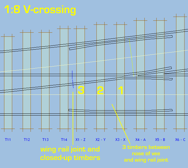
However, for "Standard Railway Equipment" (REA) designs, there are 3 timbers between the nose of the crossing and the wing rail joint, which means the joint aligns with the near end of the check rails. Here is a bit of screenshot from Templot:
regards,
Martin.
40+ years developing Templot. Enjoy using Templot? Join Templot Club. Be a Templot supporter.
-
Derek
Re: Preassembling the crossing
Can I also chip in to note that the templates from the members area of this site are under scale due to a historic scan/copy issue. There's a warning of course on the menu page, but if- like me- you follow someone's URL directly to your chosen template you might not get that warning. As for them being correct...
-
Martin Wynne
- Posts: 1172
- Joined: Mon May 14, 2012 4:27 pm
Re: Preassembling the crossing
Derek wrote:Can I also chip in to note that the templates from the members area of this site are under scale due to a historic scan/copy issue. There's a warning of course on the menu page, but if- like me- you follow someone's URL directly to your chosen template you might not get that warning. As for them being correct...
Yes, and a couple of years ago someone volunteered to correct them, and provide new files. I don't like to rush into these things...

The full discussion is here: viewtopic.php?p=28295#p28295
Sorry about that, I did do one of them: http://85a.co.uk/dummy/s4soc_b7image.pdf
Be sure to set 100% scaling or "none" when printing it from your PDF reader program.
I will try to get the rest done soon.
Martin.
40+ years developing Templot. Enjoy using Templot? Join Templot Club. Be a Templot supporter.
-
grovenor-2685
- Forum Team
- Posts: 3923
- Joined: Sun Jun 29, 2008 8:02 pm
Re: Preassembling the crossing
On the currently available template, (I am looking at a LH but assume that will be the mirror image), the joint is between sleepers 26 and 27,
Sorry but it's not. The current download has the joint between 27 and 28, leaving the 3 timbers 28, 29 and 30 between joint and nose as Martin says.
The crossing nose timber does seem to have changed from 30 to 31 when the template was corrected, can't tell why as Martin has not shown all of the older version and I don't have one of those. The lead length is still given as the same value.
Regards
-
Martin Wynne
- Posts: 1172
- Joined: Mon May 14, 2012 4:27 pm
Re: Preassembling the crossing
grovenor-2685 wrote:as Martin has not shown all of the older version and I don't have one of those.
Hi Keith,
Here you go. This matches the moulded timbering base in the Exactoscale kits. I don't know if it has since been re-tooled with a different number of timbers.
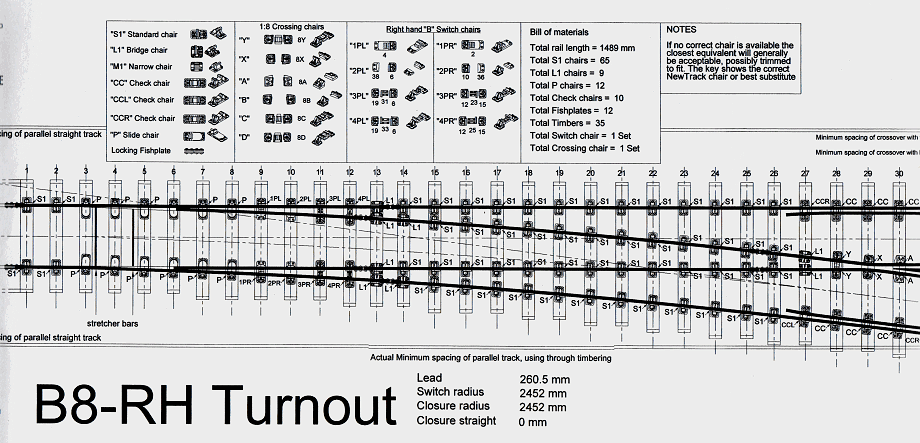
In Templot the number of timbers (fill timber spacing) is adjustable.
regards,
Martin.
40+ years developing Templot. Enjoy using Templot? Join Templot Club. Be a Templot supporter.
-
Julian Roberts
- Posts: 1394
- Joined: Sat Jan 09, 2010 11:33 pm
Re: Preassembling the crossing
Apologies Gentlemen: I have no idea why I wrote the wrong number for where the joint is on the current template.
Thank you for your assistance.
Thank you for your assistance.
-
Martin Wynne
- Posts: 1172
- Joined: Mon May 14, 2012 4:27 pm
Re: Preassembling the crossing
Here is a direct comparison of the B-8 templates.
Upper template is the current download from the Scalefour web site. Lower template was supplied with the Exactoscale B-8 turnout kits when originally introduced. I don't know if the kits are still the same. Both templates are marked with the Scalefour Society logo. I don't know which of these, if any, are currently available as prints from the Scalefour Stores.
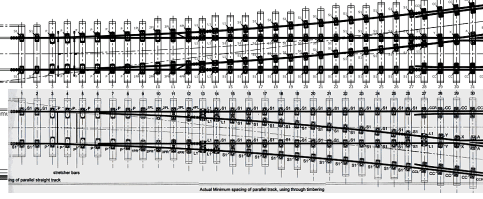
The B-switch timbers are the same spacing up to timber number 13. The current template (upper) has an additional timber in the closure space between the switch and the crossing. This will have arisen from a re-calculation of the spacings after moving the wing-rail joint position (thus increasing the closure space).
Martin.
Upper template is the current download from the Scalefour web site. Lower template was supplied with the Exactoscale B-8 turnout kits when originally introduced. I don't know if the kits are still the same. Both templates are marked with the Scalefour Society logo. I don't know which of these, if any, are currently available as prints from the Scalefour Stores.
The B-switch timbers are the same spacing up to timber number 13. The current template (upper) has an additional timber in the closure space between the switch and the crossing. This will have arisen from a re-calculation of the spacings after moving the wing-rail joint position (thus increasing the closure space).
Martin.
Last edited by Martin Wynne on Mon Nov 30, 2015 8:39 am, edited 2 times in total.
40+ years developing Templot. Enjoy using Templot? Join Templot Club. Be a Templot supporter.
-
Derek
Re: Preassembling the crossing
Martin
Would it be a sign of me being pedantic (or plain wrong?) if I was to point out that as this B8 template is based upon the LNER then it should have zero entry straight, whereas this has quite a considerable one.
(and yes I recall you telling me that there might be many reasons for non-standard ES's but as typical this shouldn't have one).
-
Martin Wynne
- Posts: 1172
- Joined: Mon May 14, 2012 4:27 pm
Re: Preassembling the crossing
Derek wrote:Would it be a sign of me being pedantic (or plain wrong?) if I was to point out that as this B8 template is based upon the LNER then it should have zero entry straight, whereas this has quite a considerable one.
Hi Derek,
I don't know what you are seeing, but both templates are marked "Closure straight 0mm". I certainly wouldn't have been able to identify whether the rail was straight from those images, so I'm wondering if we are talking at cross-purposes here?
regards,
Martin.
You do not have the required permissions to view the files attached to this post.
40+ years developing Templot. Enjoy using Templot? Join Templot Club. Be a Templot supporter.
-
Derek
Re: Preassembling the crossing
Hello Martin
I see that it shows 0mm. However, I was expecting to be able to detect where the curve starts.
In this first picture you can see that it is straight until the rail joint.
I see that it shows 0mm. However, I was expecting to be able to detect where the curve starts.
In this first picture you can see that it is straight until the rail joint.
You do not have the required permissions to view the files attached to this post.
-
Derek
Re: Preassembling the crossing
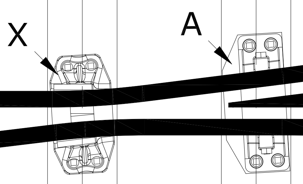
In this picture I have added a constant curve from about half way down the closure rail to the knuckle and you can see that the curve does not match the rail.
I mean no disrespect to whoever drew these (the art work is superb) and if I am wrong then I apologise, but I thought it at least worth mentioning.
I mean no disrespect to whoever drew these (the art work is superb) and if I am wrong then I apologise, but I thought it at least worth mentioning.
You do not have the required permissions to view the files attached to this post.
-
Martin Wynne
- Posts: 1172
- Joined: Mon May 14, 2012 4:27 pm
Re: Preassembling the crossing
Derek wrote:I mean no disrespect to whoever drew these (the art work is superb) and if I am wrong then I apologise, but I thought it at least worth mentioning.
Hi Derek,
These templates were created by Len Newman and are his copyright. The Society downloads are superb CAD drawings. The PDF files contain vector metafiles which can be zoomed in to show incredible detail. Even including a proper representation of the knuckle radius, which you won't find on any other templates (it's still on my "to do" list for Templot).

This fine detail is of course lost when printed at working size.
But the image you are drawing red lines on is a scan from a printed template. Which is not flat, having spent a decade rolled up inside an Exactoscale turnout kit box. I don't believe anything meaningful can be discovered from your red lines. Len clearly knows that there is no crossing entry-straight on these B-8 turnouts, and the fact is clearly stated by him on them.
The more interesting matter is to discover when the drawing was changed, which ones are now being supplied from Scalefour Stores, which ones are currently being supplied from C&L, and which ones are in the current kit production. Otherwise discussions about the error in wing rail joint position and references to timber numbers are going to get very confusing, and beginner users are potentially going to be led astray in making corrections which are no longer needed or making them in the wrong place.
Both templates are marked with the Scalefour Society logo, so members would be reasonable in assuming they are correct, wherever sourced from.
regards,
Martin.
40+ years developing Templot. Enjoy using Templot? Join Templot Club. Be a Templot supporter.
-
Julian Roberts
- Posts: 1394
- Joined: Sat Jan 09, 2010 11:33 pm
Re: Preassembling the crossing
At my beginner level, I was thinking that there would be a straight between the knuckle (timber 30) and the crossing vee (timber 31), and continuing one sleeper each way - so timbers 29 - 32 [timber numbers as per the B8-LH template] The idea was to preassemble this bit as a straight sided X.
I had seen the 'length of straight 0.00mm' but did not fully understand that and thought at my level I could ignore it. It looked straight to me at the crossing.
All I have been trying to get is a smooth running crossing and not absolute fidelity! Thanks for clarifying my issues Martin on your 9 15pm post yesterday.
-
Julian Roberts
- Posts: 1394
- Joined: Sat Jan 09, 2010 11:33 pm
Re: Preassembling the crossing
Just going back to my basic level, and to say I have got to this point.
Here is what I wound up with after several more iterations - a preassembled crossing with temporary stock rails to hold it all together rigidly, next to where the turnout timbers are stuck down on the template with gaps for the essential pcb "sleepers"
I did find that it was easier to hold up the preassembled crossing to peer down the flangeways, both roads from each end, to check how straight the run was, than it is when fixed down onto the template. But whether I would do it this way again I rather doubt, from whether the time involved is worth it.
The copperclad is slightly thinner than the ply and rivet timbers so as the crossing is soldered down, the pcb can be removed. Shame I didn't think to use rail long enough to be closure and full length stock rail too. This pic was the first trial placing with a couple of rivets soldered.
Still some bullhead turnouts to be seen on the mainline - here's one at Perth!
You do not have the required permissions to view the files attached to this post.
-
John Bateson

- Posts: 809
- Joined: Wed Jul 02, 2008 6:39 pm
Re: Preassembling the crossing
hold up the preassembled crossing to peer down the flangeways
Peering down the length gets my neck in a spasm if done too much. I now use a mirror tile angled to suit the view.
John
Slaving away still on GCR stuff ...
-
dal-t
- Posts: 654
- Joined: Mon Jan 11, 2010 8:06 pm
Re: Preassembling the crossing
Dentist's mirror also work (you can get some with telescopic handles) - except I'm convinced they add kinks to the rails. The number of times I've thought I'd laid something dead straight, only to have the mirror turn it into a wavy washboard ...
David L-T
Return to “Track and Turnouts”
Who is online
Users browsing this forum: No registered users and 0 guests