I have been preparing to build this model for some years. It presses many buttons for me:
1. 7' 01/4" Baulk road and lots of mixed gauge.
2. Victorian elegance combined with industrial grot.
3. Dual Company for operating variety and multiple liveries.
4. Exhibitable by one or max two bods; no van required; baseboards small; flexible configuration to suit various Exhibition styles/spaces.
5. Incorporates a superb model of a Brunel designed timber skew overbridge, built by the late Mike Jolly.
6. Genuine historical basis but plenty of freelance capers.
7. Opportunity to present to the unsuspecting public the first Broad Gauge models using modern techniques.....DCC, CSB, CBus etc.
So, as I have been committed to this for a while and construction has started, I pondered if it can meet the SGW criteria.....Yessss.
In due course there will be reports on progress on three fronts:
The full Dartmouth will eventually comprise 4 baseboards for the station itself + country and fiddle yard. The first two BBs will be part of my first SGW entry.
There will be a second SGW entry (!!) based on the Jolly bridge with additions to meet the SGW criteria. This will aid my thinking in how best to integrate the bridge with Dartmouth.
Finally, the combining of those two SGW models with the remaining two for Dartmouth Station together with some country boards.
Some pix show where I am at right now.
First is the MkI quarter scale mockup of Dartmouth Station showing track plan and four baseboards with major features.
The SGW entry will be the left hand two boards, but the road overbridge will need to be resited/redesigned or something for the SGW.
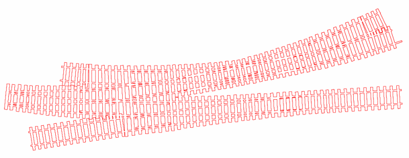
This pic shows my trial mixed gauge turnout, built to develop and prove my techniques and it was shown at Scaleforum Aylesbury. This is now my MG test track.
The CBus electronics is derived from MERG kits and will simplify wiring, allow computer control etc .
Here is my test rig, about 3/4 built. It sits on another 1/4 scale track plan courtesy of Templot. The idea is to get it all working with servos, leds etc before the modules are transferred to the real model and become less accessible, although I have planned a unique method of mounting these to mitigate inaccessibility...my spine is less flexible these days for some reason.
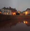
Finally here is a shot of the lovely Olton Bridge by the late Mike Jolly.
I was given this for services rendered to Broad Gauge Society and immediately decided it needs a bigger stage and bigger audience.
The model is of a real bridge designed by Brunel but never built in this form. Its location is Olton just south of Birmingham, where a different design was built with dual track mixed gauge and replaced in 20th C by a 4 track current bridge.
As Brunel had done the design it is entirely plausible that he would have flogged it to the Totnes & Dartmouth Rly Co to plug a gap near Dartmouth where a similar extreme skew was required.
Dartmouth
-
Terry Bendall
- Forum Team
- Posts: 2426
- Joined: Sun Jul 27, 2008 7:46 am
Re: Dartmouth
Looks very interesting Paul, and something a bit different.
Hummm. Hope it looks tidier under the layout.
Which Scaleforum shall we book it for?
Terry Bendall
Paul Townsend wrote:The CBus electronics is derived from MERG kits and will simplify wiring,
Hummm. Hope it looks tidier under the layout.
Paul Townsend wrote:Opportunity to present to the unsuspecting public the first Broad Gauge models using modern techniques
Which Scaleforum shall we book it for?
Terry Bendall
-
Ian Everett
- Posts: 379
- Joined: Tue Jul 21, 2009 9:43 pm
Re: Dartmouth
Paul,
this looks exactly the sort of imaginative, unpredictable response the Standard Gauge Workbench needs, absolutely fascinating.
I'm amused by your wiring - DCC simplifies wiring, does it?
Looking forward to new posts.
Ian
this looks exactly the sort of imaginative, unpredictable response the Standard Gauge Workbench needs, absolutely fascinating.
I'm amused by your wiring - DCC simplifies wiring, does it?
Looking forward to new posts.
Ian
-
Paul Townsend

- Posts: 964
- Joined: Mon Sep 14, 2009 6:09 pm
Re: Dartmouth
Terry Bendall wrote:
Hummm. Hope it looks tidier under the layout.
Terry Bendall
Cheeky s%^.
Wiring gets tidied and laced when tested here.
Terry Bendall wrote:Which Scaleforum shall we book it for?
Terry Bendall
2015
-
Paul Townsend
- Posts: 964
- Joined: Mon Sep 14, 2009 6:09 pm
Re: Dartmouth
Ian Everett wrote:Paul,
this looks exactly the sort of imaginative, unpredictable response the Standard Gauge Workbench needs, absolutely fascinating.
I'm amused by your wiring - DCC simplifies wiring, does it?
See reference to Terry as cheeky s^&
Having just finished wiring the fiddle yard "Glastonbury" for Highbridge which still uses DC techniques for consistency with the rest of the layout needed 37 and 56 way connectors, I confirm DCC does simplify wiring.
What you are seeing in the Dartmouth CBus test rig birdsnest is entirely CBus connections from switch panel into CBus modules and CBus modules out to servos with servos feedback and CBus outputs to leds. The many wire sections are contained within a single baseboard and are pretty short.
Baseboard interconnects will be 9 wires max.:
DCC track pair
CBus data pair
12volts clean power for electronics
12volts dirty for servos etc.
Screen/clean earth
I may jack up the two 12v supplies to 15v and use on baseboard 12v regulators
Looking forward to new posts.
Ian
That requires me to receive a cut from John McALeely's commission.
-
jayell
Re: Dartmouth
[quote="Paul Townsend"]I have been preparing to build this model for some years. It presses many buttons for me:
1. 7' 01/4" Baulk road and lots of mixed gauge.
ls with the remaining two for Dartmouth Station together with some country boards.
Some pix show where I am at right now.
This pic shows my trial mixed gauge turnout, built to develop and prove my techniques and it was shown at Scaleforum Aylesbury. This is now my MG test track.
Hi Paul,
What rail have you used for this and is it laid on BGS baulks, did you get info regarding the turnout from BGS?
john
-
Paul Townsend
- Posts: 964
- Joined: Mon Sep 14, 2009 6:09 pm
Re: Dartmouth
johnlewis wrote:This pic shows my trial mixed gauge turnout, built to develop and prove my techniques and it was shown at Scaleforum Aylesbury. This is now my MG test track.
Hi Paul,
What rail have you used for this and is it laid on BGS baulks, did you get info regarding the turnout from BGS?
john
I am the MembSec Committee bod for BGS and also look after 4mm trade sales.
The rail is BGS NS Bridge Rail. The baulks are dyed bass wood as I am less happy with the BGS baulks which are PCB. The society ones are easier to use in all respects but nothing looks like wood .....except wood!
BGS offer basic turnout templates for BG and MG but these ARE basic.
Templot provides some support for Baulk Road track in that an upgrade of c. 2-3 years ago introduced the feature intended for Flat Bottom rails which enables the foot of the FB rail. This can be set by user to whatever width you want so I set 20" which is correct for Baulks in turnouts.. Printouts then show baulks and railheads together.
Because Templot doesn't know about turnout design details for BG, things like crossing angles, leads, radii, switch lengths and especially guard rails (check rails to the unwashed) need a fair bit of work to adapt it to give a useful template. However, the result is better than the BGS printed templates IMHO.
BGS Members also can acquire the Society manuals re "Modelling The BG" and a file of track data sheets setting out in huge detail the prototype track parameters for both baulk and cross-sleepered BG road. (There are also a large number of excellent data sheets available for rolling stock and kits and parts galore and a few good books, see http://www.broadgauge.org.uk)
The learning curve for baulk t/o s was fairly steep for me but easier because of my considerable experience in building Highbridge (>80 turnouts using Brook-Smith rivet and ply) . I have gone through a number of trials to get the combination of techniques that work for me and deliver the result shown. I will use a couple more refinements when I get stuck into serious track building for Dartmouth this Spring.
Not shown in these pix but always on my Sales&Demo stall at exhibitions is my prototype cross-sleepered MG track using C&L plastic chairs on proper wood sleepers with soldered rivets at frequent intervals. Some of my Dartmouth track will use this since the line was a late build in BG era with running rights for foreigners as the history engages with NG LSWR in guise of the South Devon Railway as well as the BG Totnes and Dartmouth Rly Co.
Next show is RailWells August 9/10 2014, meanwhile if anyone wants a piccy of the cross-sleepered MG demo just say.
Finger extraction is essential as I have committed to show some of the boards with track as "work-in-progress" at Swindon Steam Festival in September 13-14th 2014. Whatever is viewable will also preview at RailWells.
BGS will be at Swindon in September in force with trade sales and layouts for 4mm and 7mm so do come and see what we are up to. 4mm sales only with Demo at RailWells.
Also possible (up to Terry) is an exhibiting opportunity at S4um 2015 when Dartmouth should start to look respectable and operate fully....hopefully.
-
Terry Bendall
- Forum Team
- Posts: 2426
- Joined: Sun Jul 27, 2008 7:46 am
Re: Dartmouth
Paul Townsend wrote:2015
You are now on the list for 2015 Paul, and as others have found, once you are on my list, you cannot escape.
Terry Bendall
-
jayell
Re: Dartmouth
Thanks for the comprehensive reply Paul.
I had been wondering if I should lay part of my track, ie the siding, as baulk road, but there is no photographic evidence for this being in place in Toller after the ca1906 rebuilding when the platform was lengthened, a new building was added to replace the burnt down one and at the same time a second turnout was added at the Maiden Newton end to create a loop siding and the overbridge was replaced. With all this work going on I suspect any remaining baulk road may have been removed.
I have seen two photos showing baulk road at Bridport circa 1910, one clearly showing the rail type, so it did survive for a few more years there and possibly elsewhere on the branch, the photos are on the 'Disused Lines' site as well as in the Bridport Railway book.
John
-
David B

- Posts: 1511
- Joined: Sun Jul 20, 2008 5:30 pm
Re: Dartmouth
Terry Bendall wrote:. . . . and as others have found, once you are on my list, you cannot escape.
I suggest you ask John McAleely to change your username to Ko-Ko, Terry.
(Apologies for the aside, Paul.)
-
Paul Townsend
- Posts: 964
- Joined: Mon Sep 14, 2009 6:09 pm
Re: Dartmouth
Terry Bendall wrote:Paul Townsend wrote:2015
You are now on the list for 2015 Paul, and as others have found, once you are on my list, you cannot escape.
Terry Bendall
Excellent, ta Terry.
I have been asking my local chums, when signing up to help them at shows in years ahead, to give a guarantee that I will live long enough. They all chicken out for some reason.
I now have the desired guarantee against clog-popping
I wonder what SWMBO will make of that!
-
David Bigcheeseplant
- Posts: 338
- Joined: Mon Jun 30, 2008 9:10 pm
Re: Dartmouth
Now our club has a laser cutter I was thinking if bulk road track bases and turnout bases could be laser cut in wood, using Templot to create rail and bulk positions.
David
David
-
Paul Townsend
- Posts: 964
- Joined: Mon Sep 14, 2009 6:09 pm
Re: Dartmouth
David Bigcheeseplant wrote:Now our club has a laser cutter I was thinking if bulk road track bases and turnout bases could be laser cut in wood, using Templot to create rail and bulk positions.
David
That is an idea I had too while wrestling with that test MG TO last summer.
Market would be too small to appeal commercially but club to society may be to mutual advantage. What can your club machine cope with?
I have been looking at setting myself up for laser cutting but am unlikely to cope with the sort of thick bass wood I am using at the mo, my tests have led me to using 5mm thick bass wood. There are several reasons for that thickness.
This might be a service to offer to BGS members.
It is early days yet in researching options for lasering. The more conventional 1.6mm ply would, I suppose, be more achievable on a DiY laser cutter. Specs I have seen and advice so far seems to focus on MDF in 2 or 3mm. What thickness is Brian Lewis' Timbertracks? and is it ply?
If it turns out that lasered baulks of bass wood have to be much less than 5mm thick then knock on effects need exploring, but worth doing INMHO.
For baulks I would not want to use 5mm thick ply and am not sure that I want 1.6mm ply. The point is that the sides are sometimes very visible ( more so than on cross-sleepered track) and layers look awful especially after dyeing.
This is just thinking allowed really, but ta for the poke......
-
David Bigcheeseplant
- Posts: 338
- Joined: Mon Jun 30, 2008 9:10 pm
Re: Dartmouth
The size our laser cutter can go up to is just over A3 size and can cut up to 9mm ply or MDF
David
David
-
Paul Townsend
- Posts: 964
- Joined: Mon Sep 14, 2009 6:09 pm
Re: Dartmouth
David Bigcheeseplant wrote:The size our laser cutter can go up to is just over A3 size and can cut up to 9mm ply or MDF
David
Wow, not a toy then!
I will look at producing a Templot drawing for a sample of a mixed gauge baulk road turnout set and ways of transmogrifying the output into presumably Gcode for a test run. Is there a software tool to convert a *.pdf to Gcode?
As Templot can only do part of what is required, my gut feeling is that an initial Templot file will need exporting to a Cad program to generate more detail. I suppose Sketchup would suit as it relates to tools for export to 3D printers (I have to master that caper soon) and presumably laser cutters too?
I also have Autosketch which is a cut-down AutoCad and partly AutoCad compatible for 2D work.
Activity overload between now and late January so I won't be able to spend much time on it until end of January soonest.
Meanwhile any suggestions about how to get the required Gcode from Templot welcome.
-
David Bigcheeseplant
- Posts: 338
- Joined: Mon Jun 30, 2008 9:10 pm
Re: Dartmouth
I need a DXF file for the laser cutter, I use AutoCAD at work but http://www.progesoft.com/en/products/progecad-smart/ is a free download and is a AutoCAD close and work well too. If you can export out of Templot into a DXF that would be a bonus.
David
David
-
John Palmer
- Posts: 825
- Joined: Fri Jul 15, 2011 11:09 pm
Re: Dartmouth
Templot does indeed include an 'Export DXF' option.
-
David B
- Posts: 1511
- Joined: Sun Jul 20, 2008 5:30 pm
Re: Dartmouth
David Bigcheeseplant wrote:I need a DXF file for the laser cutter, I use AutoCAD at work but http://www.progesoft.com/en/products/progecad-smart/ is a free download and is a AutoCAD close and work well too. If you can export out of Templot into a DXF that would be a bonus.
David
Another freebie is Sketchup which was used last October at Missenden Abbey's weekend. Bob Gledhill, the tutor, has made his notes on the use of Sketchup available for people to download which they can from the Missenden Modellers' website.
David
-
Paul Townsend
- Posts: 964
- Joined: Mon Sep 14, 2009 6:09 pm
Re: Dartmouth
Yes I know about Sketchup as mentioned in a couple of posts up.....recently installed here and beginning to tinker.
Looks like the quickest route for me will be Templot Baulks as basis then export as .dxf
Into either Autosketch which accepts some versions of .dxf ; easy for me as I have a licensed version and rusty familiarity. I have interchanged Templot and Autosketch files a year or three ago in developing the background for Dartmouth plan so must find those notes! It certainly worked with Autosketch as source for Templot, don't recall needing the reverse.
OR into Sketchup 2013 freebie, less easy here as I am new to this one but need to learn it for 3D print capers, however Cad is Cad is Cad!
In whichever Cad program, edit the DXF to improve Templot version and resave it.
Now I know from experience that .dxf has many flavours and there are many incompatibilities so I propose to create a very simple drawing in both Autosketch and Sketchup, send those two files to David BigCheese as a trial run.
No need to laser cut anything at that stage, just check that your club software accepts these files. Then no-one wastes time on unuseable work.
Stage two would be a simple turnout base to check the cut wood resembles the "drawing", this won't happen so quickly.
This quickish first task may happen PDQ, hopefully on Easyjet and Treni-Italia to/from Firenze, Tuscany for Costanza's imminent baptism or while rotting in Gatwick in return journey awaiting connection to Bristol.
-
David Bigcheeseplant
- Posts: 338
- Joined: Mon Jun 30, 2008 9:10 pm
Re: Dartmouth
There are quite a few free CAD programmes out there I did try using DoubleCAD but the exported DXF files could not be read by the laser cutter software, but ProdeCAD there was no problem.
I have downloaded Sketchup but have Autodesk Inventor at work which I love but at £6000 it's something most personal users could not justify. Generally a 2D programme will be fine for most of our needs.
David
I have downloaded Sketchup but have Autodesk Inventor at work which I love but at £6000 it's something most personal users could not justify. Generally a 2D programme will be fine for most of our needs.
David
-
jayell
Re: Dartmouth
Paul Townsend wrote: ....................... however Cad is Cad is Cad!
I wish
It is now some 20 years since I last used GenericCAD on a daily basis and occasionally made use of a 'dongle free' version of AutoCad release 9 for which version I still have a copy of 'Inside AutoCAD' (published in 1988 which sort of confirm how long ago it was) and I thought it would be easy enough to start using open source software like FreeCAD or LibreCad, but I find them quite baffling, partly I guess because the CAD packages I used at work were DOS based so there were no fancy gui interfaces to confuse things.
So Ithought to meself 'lets try this progecad-smart thingummy' since it is an AutoCAD clone and my might give me more guidance than the sparse to non-existant documentation that opensource software often comes with
So I woke up my sleeping Win7 box intending to download progecad only to find that the first thing on offer was a free download of AutoCAD 2014. I don't know what the restrictions are on use of this 'free' version but I did see that I can buy a copy of version 2008 for £18.
I don't know why, but I expect my slow internet connection has something to do with it, but the down load has stopped at 55% and windows seems to have gone back to sleep, did I mention that I hate windows!
Anyway having killed the browser and restarting it the download is restarting from the beginning - doh!
john
-
jayell
Re: Dartmouth
Having downloaded the .exe file and extracted the installer from it I then find it is a 64 bit version and I only have a 32 bit Win7 system. Usually download pages are 'intelligent' enough to choose the correct version for the computer it is to be installed on so that is a bit annoying. Cannot do anything more for now as windows has decided it is time to install some system upgrades, so it will proabably want to reboot.
Give me Linux everytime, I do an daily, automated, download of any upgraded packages during the night and install them as my first job of the day. I have upgraded probably a hundred packages so far this week and none required a reboot. Normally the only thing requiring a reboot will be a new version of the kernel, and that will be at a time of my choosing.
/rant over
john
-
Phil O
- Posts: 364
- Joined: Sun May 05, 2013 5:23 pm
Re: Dartmouth
johnlewis wrote:Paul Townsend wrote: ....................... however Cad is Cad is Cad!
I wish
It is now some 20 years since I last used GenericCAD on a daily basis and occasionally made use of a 'dongle free' version of AutoCad release 9 for which version I still have a copy of 'Inside AutoCAD' (published in 1988 which sort of confirm how long ago it was) and I thought it would be easy enough to start using open source software like FreeCAD or LibreCad, but I find them quite baffling, partly I guess because the CAD packages I used at work were DOS based so there were no fancy gui interfaces to confuse things.
So Ithought to meself 'lets try this progecad-smart thingummy' since it is an AutoCAD clone and my might give me more guidance than the sparse to non-existant documentation that opensource software often comes with
So I woke up my sleeping Win7 box intending to download progecad only to find that the first thing on offer was a free download of AutoCAD 2014. I don't know what the restrictions are on use of this 'free' version but I did see that I can buy a copy of version 2008 for £18.
I don't know why, but I expect my slow internet connection has something to do with it, but the down load has stopped at 55% and windows seems to have gone back to sleep, did I mention that I hate windows!
Anyway having killed the browser and restarting it the download is restarting from the beginning - doh!
john
Hi John,
Can you post a link for the AutoCad please.
Cheers Phil
-
jayell
Re: Dartmouth
Phil O wrote:Can you post a link for the AutoCad please.
Cheers Phil
yer tis!
http://www.autodesk.co.uk/products/auto ... free-trial
And I have now spotted the option for a 32 bit version
john
-
Martin Wynne

- Posts: 1172
- Joined: Mon May 14, 2012 4:27 pm
Re: Dartmouth
Paul Townsend wrote:Templot provides some support for Baulk Road track in that an upgrade of c. 2-3 years ago introduced the feature intended for Flat Bottom rails which enables the foot of the FB rail. This can be set by user to whatever width you want so I set 20" which is correct for Baulks in turnouts.. Printouts then show baulks and railheads together.
Hi Paul,
This will result in curved timber baulks. May I suggest that you use the FB rail option for its intended purpose to show the base of the bridge rail?
And then use the timber shoving functions to put the straight baulk lengths under the rails.
For some notes about laser cutting from Templot templates, see:
http://85a.co.uk/forum/view_topic.php?i ... id=1#p4491
http://85a.co.uk/forum/view_postx.php?post_id=4515
(All a bit out of date now.)
Martin.
40+ years developing Templot. Enjoy using Templot? Join Templot Club. Be a Templot supporter.
Return to “Standard Gauge Workbench”
Who is online
Users browsing this forum: No registered users and 0 guests