Buck Jumping on Mass

User avatar
Will L
Posts: 2527
Joined: Sun Jul 20, 2008 3:54 pm

Re: Buck Jumping on Mass

Postby Will L » Mon Dec 02, 2013 11:31 pm

essdee wrote:those who would like to be able to dismantle - or at least feel free to be able to dismantle - the gearbox wheelset, you might find Tom Mallard's neat solution on p 130 of MRJ No.223 of interest


How did I miss that? Thanks for pointing it out Steve. It appears that for want ever reason, while I had read everything else in that issue, I had entirely failed to read that particular article until you pointed out its relevance. A pity as I suspect his wise words on not over tightening the screw press when fixing the wheel on the stub axle may have saved me a wheel or two.

The frame he illustrates to allow wheel removal is obviously the right thing, although I do wonder how practical it will be on driving wheels significantly larger than those fitted to Tom's O2 or my J56 & 59. It will have to be made out of something pretty robust. I am feeling mildly smug about finding an easy solution to the problem of the press turning the wheel that hadn't apparently occurred to Tom, and something C&L could implement on the press tools they sell very easily.

Will

User avatar
Andy W
Posts: 884
Joined: Thu May 21, 2009 8:11 am

Re: Buck Jumping on Mass

Postby Andy W » Tue Dec 03, 2013 12:10 pm

A very interesting thread Will. Overall would you use these wheel-sets again if there was an alternative supplier?
Make Worcestershire great again.
Build a wall along the Herefordshire border and make them pay for it.

User avatar
Will L
Posts: 2527
Joined: Sun Jul 20, 2008 3:54 pm

Re: Buck Jumping on Mass

Postby Will L » Tue Dec 03, 2013 4:58 pm

Ealing wrote:A very interesting thread Will. Overall would you use these wheel-sets again if there was an alternative supplier?


If they were the correct wheel for the job and they weren't available from else where. Definitely. If I had a real choice, interesting question, probably to soon to be sure.

Will

User avatar
Will L
Posts: 2527
Joined: Sun Jul 20, 2008 3:54 pm

Re: Buck Jumping on Mass

Postby Will L » Thu Jan 23, 2014 5:27 pm

Hi Guys, just an enquiry this time. Can anybody give me details of the Air reservoir, and possibly Westinghouse brake cylinder which are just about visible under the rear buffer beam of many Buckjumpers, including the preserved example which is currently at Bressingham I believe.

Will

Tor Giffard

Re: Buck Jumping on Mass

Postby Tor Giffard » Fri Jan 24, 2014 2:07 pm

Aft'noon all,

....lovely part of the world around Upwell Will...we've travelled through many times on our Staffs Moorlands to Felixstowe via the scenic route meanderings. Looking forward to checking out your progress.

Dave

Eastern
Posts: 23
Joined: Fri Aug 14, 2009 7:36 am

Re: Buck Jumping on Mass

Postby Eastern » Fri Jan 24, 2014 6:27 pm

Will L wrote:Hi Guys, just an enquiry this time. Can anybody give me details of the Air reservoir, and possibly Westinghouse brake cylinder which are just about visible under the rear buffer beam of many Buckjumpers, including the preserved example which is currently at Bressingham I believe.

Will


HI Will,

Details of these seem to be hard to come by. GERS drawing L25 (R24 rbt) shows an air reservoir on the left hand side and a brake cylinder on the right on top side and end views; no dimensions though. The drawing does however tie up with rear end photographs that I have seen in various publications. There is a good view of the air reservoir on page 99 of Yeadon's Vol 48; you can also see the sloping straps that supported the rear of the brake cylinder from the rear buffer beam (but not the cylinder itself). There must be some works drawings around somewhere, but how you can get them, I don't know.

I'm not sure if that helps any.

Roger

User avatar
Will L
Posts: 2527
Joined: Sun Jul 20, 2008 3:54 pm

Re: Buck Jumping on Mass

Postby Will L » Sat Jan 25, 2014 12:24 am

Eastern wrote:Details of these seem to be hard to come by. GERS drawing L25 (R24 rbt) shows an air reservoir on the left hand side and a brake cylinder on the right on top side and end views; no dimensions though. The drawing does however tie up with rear end photographs that I have seen in various publications. There is a good view of the air reservoir on page 99 of Yeadon's Vol 48; you can also see the sloping straps that supported the rear of the brake cylinder from the rear buffer beam (but not the cylinder itself). There must be some works drawings around somewhere, but how you can get them, I don't know.


Thanks for that Roger, I have been given to understand that there are no extant works drawings for the Buckjumpers. I will have to see about obtaining the GERS drawing. I found the photo in Yeadon today as it happens, much searching on the net has also produced a rear view of J69 no 87 in preserved form which also shows what you describe. I suspect that the J65 were similarly configured but I have yet to find a photo that makes that certain, the brake rigging was clearly very similar. Of course I have got to the J65 chassis detailing before the J69.

Will

mikeg

Re: Buck Jumping on Mass

Postby mikeg » Tue Jan 28, 2014 9:01 am

Paul - just in case you are still into the Hadleigh branch below is a picture taken yesterday of Raydon station building which is coming close to completion of rebuilding. The yard is the local coal depot where I get my winter fuel. Thought you might like it as it will probably come on the market soon and you said you were looking for a larger house!!
You do not have the required permissions to view the files attached to this post.

User avatar
Will L
Posts: 2527
Joined: Sun Jul 20, 2008 3:54 pm

Buck Jumping on Mass - The Build Phase

Postby Will L » Fri Mar 04, 2016 11:21 pm

Part 1– Let battle commence

So at last, as promised, I return to the construction of the J65 and J69, if rather later in the day/month/year/decade than I intended when I wrote the last post. You may need to do some revision to remember where we had got to, but don’t get too excited yet. Before we actually build anything we better have a good think about the exact prototype we want to produce and do some basic planning.

Having arrived at the position that I was going to set about both the J65 and the J69, it was obvious to me that I should do the two in parallel. I generally find batch building improves the speed of progress, from glacial to snail’s pace its true but it is an improvement. They were, after all, very similar prototypes and both kits were produced originally under the Riceworks banner. I got my J65 kit direct from President Ian mumble mumble years ago, but the J69 came from London Road Models much more recently. Both are etched kits with lost wax and white metal castings, and a brass Tube cut to length for the boiler. Reading both sets of instructions in parallel gives you a very distinct sense of dèjá vu.

The Prototype

Before I started building I thought I should have a fair idea what the particular locos I was going to build would looked like, especially as I was building Stratford prototypes that underwent a significant amount of detail change over time. My chosen date is 1934, and given the set of fixtures and fittings I wanted to include, I tried to find two locos that fitted the bill. This didn’t prove all that easy and I soon realised that some of my original ideas could easily have produced a historical anomaly. After a lot of head scratching, compromise and consideration I settled on the following.

The J65

No 7155 as it would have looked in early 1934 just before it had a boiler change.
One of the first 10 built in 1889 to order E22, and one of the last survivors not being withdrawn until 1953.
4’0” 10 spoke cast steel wheels with distinctive balance weights (infill between spokes rather than crescents).
Strait brake pull rods.
Low roof (7155 never got a high one)
Diagram 36 boiler, with twin column Ramsbottom Safety valve, over the firebox and with the whistle on the same seating as the safety valve
Stovepipe Chimney
Westinghouse fitted
In filled coal rails
Blower valve on the smoke box controlled by a rod running above the hand rail
Tool box on left tank top hard against the cab
GER parallel buffers
Steam heating fitted with “bags” on, it must be winter.
Running as a 2-4-0, as it did for much of its life. To start with I assumed it had reverted to a 0-6-0 when it stopped working the Blackwall service just like most of it classmates, and it was quite late on that I realised that the photo evidence suggested otherwise. The decision to go 2-4-0 was taken quite late and the chassis was originally built as an 0-6-0 as some of the pictures will show,
There is a good picture at the right period on Page 20 of Yeadon Vol 48, also several others at different dates.
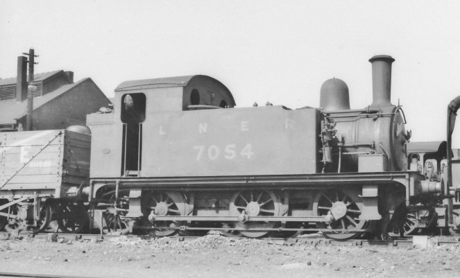
The J69

No 7054 in early 1934, not long before it acquired a high cab roof.
One of the first 10 built to order S56 in 1904, sold to the MOD in 1940, and sold again into industry in 1946. Scraped 1954.
4’0” 10 spoke cast steel wheels with crescent balance weights.
Strait brake pull rods
Originally fitted with condensing gear but this was blanked off in 1930
Diagram 37 boiler with Ross pop safety valves forward of the firebox, whistle mounted close to the cab font.
NE pattern Chimney
Low Cab roof
Westinghouse and Vacuum fitted
Injectors behind cab step
Blower valve control through left hand handrail
No tool box
LNER Standard stepped buffers
Again Steam heat ready.
Picture in RCTS vol 8A Fig 92.but with high roof fitted post 1934.
Image

The logical first step was to do the chassis. Those who know me will realise that this implies we are off to the land of CSB suspension. I decided that the order of play would be, to do the basic rolling chassis first, then build up the body to the point where the space available for the drive train was well understood, then complete the chassis, drive train, pickups and all before completing of the body shell.

Information Used

To support this build, the most important sources I used were

Yeadon’s Register of LNER Locomotives Volume 48
RCTS Locomotives of the LNER Part 8A
MRJ 35 &36 Ian Rice's article “In Search Of The Buckjumpers”. Including Lyn Brooks drawing for the GER society of the R24 and R24R variants of the J67/9s
Model Railways, March 1972 portrait of a Locomotive No 87 (S56) including Bernard Wright’s sketches of various parts of the preserved example.
And Finally and perhaps a little late in the day, the John Gardner loco drawings, derived from the Stratford originals, and published by the GER society. These became avaible available in 2020 as a full downloadable collection that covers most GER locos in general and Buckjumpers of all varieties in particular.

Edited to add the John Gardner drawings to the Information Sources used
Last edited by Will L on Wed Apr 14, 2021 10:54 am, edited 1 time in total.

User avatar
Will L
Posts: 2527
Joined: Sun Jul 20, 2008 3:54 pm

Buck Jumping on Mass - The Build Phase

Postby Will L » Mon Mar 07, 2016 7:36 pm

Part 2 -The Chassis Basics

The chassis specification for both locos is as follows. Exactoscale GER 4’00” 10 spoke wheels, CSB suspension using Highlevel horn blocks, a Mashima 1024 motor (my favourite), and a Highlevel Slimliner gearbox with 54:1 gears and a Drivestretcher. This gives my favoured drive configuration, with the motor horizontal in the boiler, the gear box vertical in the firebox, and the Drivestretcher taking the drive under the cab floor to the rear axle. According to the speed calculator available on the Highlevel web site, the 54:1 gearing taken together with the 4’0” wheels and the 1024 motor give you a scale top speed of 50mph. This seemed in keeping with a prototypes which was noted more for acceleration than top speed. Using the Slimliner gearbox meant that it would fit between standard Highlevel axle bearing blocks without any issues, which is not true of some Highlevel gear boxes.. The pick-ups were going to be top wipers, running on top of the wheel treads and, in the case of the front wheel, close beneath the underside of the footplate.

Will it fit?

The objective of starting the body before completing the powered chassis was to ensure that the whole drive train would fit in the open area enclosed by the side tanks and not intrude into the cab. The exact profile of the cab interior was not easily apparent without making up the body and it was uncertain if or how far down the boiler barrel beyond the tanks the motor would have to go. The J69 looked to be no problem, but not so the J65 as the 1024 is quite a long motor and it would have to go a little way down the boiler beyond the side tanks. I wanted to be sure it was actually possible to fit the chassis + motor into the body, given the way the bodies and chassis were designed to fit together. Again something you couldn’t be entirely certain about until you’ve got the basic built up body to play with. This picture jumps us forward in time to show 7155 at this stage along with its portrait from life.
Buck 65 C-B fit.jpg


The Chassis Kits

The J65 kit comes with a bespoke chassis, the J69 comes with a chassis kit, designed by Rod Neep to fit under various other J67 to J69 kit offerings that have existed over time. Although clearly sharing a common heritage, these two chassis kits weren’t perhaps as similar as one might have expected. Both follow the Rice-ian approach of being held on by bolt at one end only, the other end slotting into the body shell in one way or another. Our Mr Rice comes from the view that while the body tends to be more structurally robust than the chassis there isn’t the same incentive or ability to get it totally square and flat as there is with a chassis. Therefore if you bolt a nice square chassis firmly down to a slightly less than square body at both ends, you run the risk of distorting the chassis out of true. So, just to be different, the J65 chassis slots in behind the front buffer and bolts up under the bunk and the J65 slots in under cab and bolts up into the smoke box.

Of course the biggest difference between the two kits is a subtle 6 inch difference in wheel base. As I was planning to build the chassis in the “Chassis Pro” jig which has to be set to the wheelbase of the chassis, basic assembly was clearly going to have to follow a one at a time approach and lump it. However this description will cover the assembly of both in parallel.

The CSB bit

Given you have an existing chassis kit, the very first job on an CSB chassis is to work out the fulcrum point positions. Clearly in working these out one should take into account the structure of the chassis so as to ensure the fulcrum points don’t conflict with any other feature of the chassis. The very first thing that struck me when considering the J65 was a couple of large weight saving cut-outs in the side frame which seem set to coincide with two of the four fulcrum points no matter what I did. The J69 chassis has similar but smaller cut outs which don’t pose the same problem. I haven’t been able to ascertain if either or both are fully in line with the prototype, the J65 was after all a more lightly built loco and might just have deserved and received bigger frame cut-outs. What I did about not having anywhere to put 2 of the four fulcrum points on the J65 I will explain when we get there

For the record:-

The J65 chassis

Has a wheel base of 6’4” + 7’0” (25.33r + 28 in millimetres)
and has its fulcrum points (Fn) set out around the axles (An) as follows
F1-10.5-A1-11.83r-F2-13.5-A2-15.5-F3-12,5-A3-9.5-F4

The J69 chassis

Has a wheel base of 6’4” + 7’6” (25.33r +30 in millimetres)
and has its fulcrum points (Fn) set out around the axles (An) as follows
F1-10.5-A1-12.33r-F2-13-A2-17-F3-13-A3-9.5-F4

For those of you wondering quite how I dealt with dimensions expressed to an accuracy of .33 recurring, the honest truth is that I didn’t. I just assumed the kit designer had got the axle spacing close enough and measured that fulcrum from the other axle to the normal level of accuracy (0.5mm) so lets assume that in this case r = roughly.
You do not have the required permissions to view the files attached to this post.

User avatar
Will L
Posts: 2527
Joined: Sun Jul 20, 2008 3:54 pm

Buck Jumping on Mass - The Build Phase

Postby Will L » Mon Mar 14, 2016 4:03 pm

Part 3 – Chassis preparation for CSB

For our next trick, we are going to cover the basic preparation of the chassis for the fitting of CSBs. This seems a good point to have an illustration of the J65 chassis fret. While the J69 chassis was different in some marginal detail the process was essentially the same. The fret has to be marked out and drilled for the CSB fulcrums before doing anything else. The blacking is just black spirit marker, and the fulcrum centre lines, horizontal and vertical, have been scribed in. You can also see three holes above the fulcrum line which are for the break gear and which I found, when I came to it, are etched in the wrong place. The separate etch brass thing at the top of the picture is the Highlevel CSB Drilling jig which will come in handy as we go along.
Buck j65 chass etch 3.jpg


A Little CSB Revision

The fulcrum point centre line is set out parallel to and (usually but not necessarily) above the axle centre line. The distance between the two being 0.5mm less than the distance between the axle block centre and the fulcrum point fixed to it, thus giving a 0.5mm static deflection on the CSB when fitted with a CSB wire matched to the loco’s weight.

To mark out the positions of the fixed fulcrums on the chassis frames from first principles you have to
1. mark up the axle centre lines, both vertical and horizontal;
2. decide how far above the axle centre line the fulcrums are to be mounted, (the CSB carrier tags provided by Highlevel to go with their horn blocks give you 3 choices);
3. mark in the fulcrum points horizontal centre line, that far above the axle centre line;
4. along that line, mark the fulcrum points proper by measurement from the vertical axle centre lines.

Practicalities

When scratch building a chassis, defining the horizontal fulcrum point centre line is just one more simple step, as the axle centre lines are the basic datum lines from which the rest of the chassis frame is drawn. When doing the same job on an existing etched chassis kit, accurately establishing exactly where the axle centre line should be, and marking it in, is far less trivial. After a couple of goes I decided “b**** that for a game of soldiers” and purchased the Highlevel CSB drilling jig which happily sorts all this out for you. The jig plugs itself into the existing axle holes in the chassis and allows you to set out the fulcrum points for each axle with little further ado. You can see the tutorial that Highlevel have provided on using this jig here.

Using this jig, you drill out a .5mm hole for each fulcrum point. This worked fine on the J69 where there was plenty of metal to drill into. On the J65, for two of the four fulcrum points, all there was was empty air, as any reasonable fulcrum point coincided with weight reduction holes cut into the frames. That required a bit of thought. What I did about it will become clear when I cover fitting the fulcrums, which may well be several posts further on. The scribed lines on the fret in the above picture are the fulcrum point horizontal and vertical centre lines. The jig allowed me to establish the vertical line for the missing ones. These scribe lines are a useful guide, when fitting the fulcrums, to make sure the fulcrum point proper is vertically above the hole in the chassis, as well as enabling me to deal with the missing ones.

What the J69 did have that the J65 does not, was etched holes for sprung plunger pickups, and these came fairly close to where the fulcrums wanted to go. This sort of pickup is just incompatible with any form of suspension, compensated or sprung, to say nothing of acting like brakes. So on the J69 chassis, before the fulcrum points were drilled, the sprung plunger pickup holes were eliminated by having an appropriate size bit of brass wire soldered in and filed flush. Both loco’s also had holes etched for a compensating beam pivot, these too were filled with wire and solder and filed flat..

The Highlevel jig also allows you to drill a hole into the chassis side frame so you can, using a wire pin, accurately position a Highlevel horn guide etch on the side frames using a matching hole etched into the horn guide. However, remembering that we are going to assemble the chassis in the “Chassis Pro” jig, you should only pin the middle horn guide on each side, as the exact distance between the axles will be set by the Chassis Pro and you don’t want two different methods of setting the horn guide positions to argue with each other.
You do not have the required permissions to view the files attached to this post.

User avatar
Will L
Posts: 2527
Joined: Sun Jul 20, 2008 3:54 pm

Buck Jumping on Mass - The Build Phase

Postby Will L » Fri Mar 25, 2016 1:16 pm

Part 4 – Preparing The Highlevel Horn Blocks…

…or whatever it is we should really call them. The picture shows you half the bits (1½ axle worth) we need for one loco.

buck chass 4.jpg

First we need to bend up the Highlevel horn guide etches, the bits at the top of the picture. These are designed just to be folded up only, no solder required. You are advised to believe this as any attempt to know better tends to gum up the works. Guess how I worked that out. Then select an axle bearing block to go with each horn guide (the middle bits). Polish what will be the two vertical edges of each block so they are a tight but smooth sliding fit in the horn guide. Once a block is matched to a horn guide they should stay as a pair and always be assembled together and with the block the same way up. I mark, with a good healthy centre pop, what I have (arbitrarily) decided is going to be the bottom of each block, where you can see it when they have been assembled,. Half have one pop and half have two. Bits with one pop mark end up on the left hand side of the chassis and those with two the right. Marking them now ensures everything continues to go together the right way round throughout the chassis life. It may be helpful to mark which axle it will belong to too but not just yet.

Highlevel axle bearing blocks come in two different thicknesses. I’m using the original standard size, which are relatively thick (standing back about 3.5mm from the outside face of the frames), and, as the picture of the assembled axle/gearbox shows, the driven axle gets quite crowded. The Buckjumpers are Ok because my chosen drive train , a Highlevel Slimliner gearbox fitted with a drive extender, is narrower than most Highlevel gearboxes and it all fits in P4. Users of lesser gauges or other gearboxes need to be sure they have the necessary room between the frames before they get to far. Highlevel do special slim axle blocks (2.2mm) if there is a problem.

buck chass 11.jpg

Next we bend up the Highlevel CSB carrier tags (the bottom bits in that original picture) to provide the axle bearing block CSB fulcrum. The etch fits over the rim round the axle hole on the block and is then attach with solder, making sure that the centre popped side of the axle block is at the other end from the CSB fulcrum. Assemble the finished axle block and horn guide pairs and use a little keeper wire through the holes provided to ensure the pair stay together while building is in progress. You can use these keeper wires in the finished chassis, if your using these horn blocks for other suspension systems, but it isn’t necessary with a CSB as the spring wire through the fulcrum does the job just as well.
buck chass 3.jpg

At the end of the job you finish up with a set of these. You may notice there is one little additional piece on each one which I haven’t mentioned yet. I will explain next time.
You do not have the required permissions to view the files attached to this post.
Last edited by Will L on Sun Apr 05, 2020 6:24 pm, edited 1 time in total.

David Thorpe

Re: Buck Jumping on Mass

Postby David Thorpe » Fri Mar 25, 2016 4:16 pm

I've not yet been able to work out how to use the High level jig. You say: " The jig plugs itself into the existing axle holes in the chassis", which basically echoes High Level's instruction to "slot the master bearings through the holes in your frame", which accompanies a picture of a rigid frame with holes for the axles. The trouble is that none of the frames I use have holes - almost invariably they come with the holes replaced by cut outs for horn guides. In such a situation it seems that the High level jig is, sadly, pretty useless - unless, of course, I'm missing something, which is quite probable.

DT.

User avatar
Will L
Posts: 2527
Joined: Sun Jul 20, 2008 3:54 pm

Re: Buck Jumping on Mass

Postby Will L » Fri Mar 25, 2016 5:14 pm

David Thorpe wrote:I've not yet been able to work out how to use the High level jig. You say: " The jig plugs itself into the existing axle holes in the chassis", which basically echoes Highlevel's instruction to "slot the master bearings through the holes in your frame", which accompanies a picture of a rigid frame with holes for the axles. The trouble is that none of the frames I use have holes - almost invariably they come with the holes replaced by cut outs for horn guides. In such a situation it seems that the High level jig is, sadly, pretty useless - unless, of course, I'm missing something...


David

The Highlevel jig does come with an adaptor plate which fits in the standard 6mm by 7mm horn block cut out and replaces the missing axle holes so you can still make use of the jig. That said as you have a flat line you can draw along the top of the cut outs which should be 4mm above the axle centre line, it isn't that hard to mark out the fulcrum point centre lines, as I explained here.

David Thorpe

Re: Buck Jumping on Mass

Postby David Thorpe » Sat Mar 26, 2016 10:41 am

I'm afraid that I find the use of the adaptor plates a bit convoluted. I find the easiest and most effective way of fitting CSBs (for me at least) is the one set out on the CLAG site using (MJT) hornblocks and Markits handrail knobs. I'm also not sure why there are three (or four) holes in the High Level CSB carrier tags - if you start by measuring so that the fulcrum points give a 0.5mm deflection, why do you then need a choice of holes in the carrier tags?

DT

SHurst

Re: Buck Jumping on Mass

Postby SHurst » Sat Mar 26, 2016 12:44 pm

David

Quite simply the choice of "marker holes" on the jig and corresponding "slots" on the hornblock tags allows for the height of the CSB wire to be varied to avoid possible obstructions such as brake hangers etc. Clever really. ;)

Simon

David Thorpe

Re: Buck Jumping on Mass

Postby David Thorpe » Sat Mar 26, 2016 5:33 pm

Thanks, Simon - got it. Stupid of me not to have realised that. Maybe I'll give them another go.

DT

User avatar
Will L
Posts: 2527
Joined: Sun Jul 20, 2008 3:54 pm

Buck Jumping on Mass - The Build Phase

Postby Will L » Sun Mar 27, 2016 11:52 am

Part 5 - Preparing the Frames for the Hornblocks

Once the frame sides are drilled/marked up as necessary the next step is to cut out the standard 7mm by 6mm U shapes into which the Horn Guides will fit. Both chassis had the top edge of each hole etched in, as the picture of the J65 chassis etch two posts back shows, so just a couple of vertical cuts does the job. You will also notice that the frames, as etched, have spring detail below the axle holes. These have to come off too, if it is going to be possible to drop the axles out without disassembling the wheels and axles in later life.

The ability to drop the axles out in this way is “A Good Thing”, and much to be encouraged. The posts earlier in this thread, which give details of the Exactoscale wheels that go with this project show drop out wheel sets to be highly desirable. (These posts are now over 2 years old so you might need to refresh your memory, starting here ). The same is true if you use Gibson wheels which are best not removed from the axle once fitted, because, if you do they tend to become loose on their axles and you will end up needing to pin them on to retain gauge and quartering. One of the significant advantages of this CSB approach is that a basic part of the package is wheels that are simple to drop out of the chassis.

Reinstating The Spring Detail

Having removed the spring detail from the frames, we are, of course, going to want to reattach it somehow. There are various ways of doing this, and in the past I have generally mounted them on a keeper plate. The thing is that this sort of CSB installation doesn’t need anything under the axles to keep them in, as the CSB wire does that job nicely. Nor do I need anything similar for the pickups as they are going on top of the chassis above the wheels, so I have thought for some time that there has to be a better way. Then I spotted a dodge used by the late lamented Adrian Prescott (may his memory be for ever burnished and neatly lined). He simply attached the spring detail to the bottom of the axle bearing block. Just why I couldn’t have thought of that one for myself I’ll never know.

On the J65, whose bits were illustrated in the last post, I soldered a bit of 1mm strip brass into the slot on the bottom of the axle block in the early stages, the unexplained extras from the last post, and then soldered the Spring detail to that much later in the process when it was possible to see exactly where they needed to go. This wasn’t so clever as it proved hard not to unsolder the 1mm strip from the axle block while trying to solder on the spring detail, even if I used high and low melting point solders. It wasn’t that easy to get them square and straight either. Just to prove that I do learn from experience, for the J69 I soldered the spring detail to the 1mm strip first (using 212 degree solder), then soldered that assembly to the axle block with 188 or 145 solder, holding the joint between strip and spring detail in a pair of flat nosed pliers while I did it. This proved much easier to do. The photo of the J65 below, which was taken when I had just finished adding the spring detail, shows the finished effect.

buck chass 9.jpg


Coupling Rods

We’re nearly there now, all that is left is to assemble the coupling rods so we can use them to set up the Chassis Pro jig. The coupling rods are articulated on the middle crank pin. This isn’t a compromise to avoid having to make proper articulated coupling rods, it is exactly how the GER did it. Both kits have two layer etched rods which were soldered together and checked to ensure the two sides were the same. The rods for the left side are centre popped, on the back, once and those for the other side are popped twice. Probably not really necessary as they are handed and you ought to be able to tell which is which, but I find it helps. Now, as shown here, we have (almost) all the bits needed to start assembling the chassis sides.

buck chass 2.jpg

The next step is to set up the jig, which as it is critical to a good running chassis is worth a post all of its own. Coming next.
You do not have the required permissions to view the files attached to this post.

User avatar
Will L
Posts: 2527
Joined: Sun Jul 20, 2008 3:54 pm

Buck Jumping on Mass - The Build Phase

Postby Will L » Fri Apr 15, 2016 11:20 am

Part 6 Setting up the Chassis Pro Jig

In the good old days I used to use single axle jigs to assemble chassis. This meant assembling the chassis sides and spacers as square as possible using a flat surface and a set square, then fitting the horn guides to the sides using the single axle jigs spaced out with the coupling rods. That works OK but the advent of the Chassis Pro changes the sequence rather, and once the rods are done its time to set up the jig. This section seems to have turned itself into a bit of a Chassis Pro teach in but perhaps there is nothing wrong with that.

Buck jig 1.jpg

The first picture shows you the basic chassis pro set up for the J65 with three axle pins in place (the jig will take up to 5). Set up properly, the jig ensures the axle pins are in line and parallel to each other, the right distance apart and truly at right angles to a work surface you can build the chassis on. The guides or fences above and below the axle pins can be set using millimetre scales marked on the jig so they are parallel to the axle pins.

The second picture shows the underside so you can see what you are dealing with.
buck jig 6.jpg

The axle pins can be either short, to do work on one chassis side or long to assemble the whole chassis. You start out with the short pins and set them to match the coupling rods. This needs doing with care and there are snags which can trap the unwary. The jig’s axle pins screw into the cross pieces you can see above which are in turned spaced the right distance apart by the screw adjusters on the end, then set screwed into place in the main frame of the jig (see read arrows in the picture below). The instructions say the axle pins must be screwed in finger tight, but I found that there is a danger they will then slacken off and move marginally while the jig is in use. As you don’t want to damage the surface of these pins, you can’t grip them firmly enough to screw them up tight from above. Fortunately they have a small screwdriver slot in the lower end (see blue arrow below) which should be used to tighten them a little more firmly into the cross piece. A small screw drive is required to do that, and there is no need to over tighten.

Buck jig 2.jpg

The second snag-ett comes when setting the axle pins the right distance apart using the coupling rods. As you do up the set screws (red arrows) the action of tightening the screw can cause the end of the cross piece to move slightly. You should have set up so the coupling rods slide easily off the axle pins. Once you’ve tightened up the set screws it can suddenly become more difficult to get the coupling rods off, a sure sign that the cross pieces have moved just a little bit as you did up the set screws. So do up the set screws carefully and keep on testing the fit of the rods, you’re not done till they are done up tight and the rods still slip on and off easily.

Buck jig 3.jpg

Obviously when you’ve set up the jig with one set of rods you should make sure the other set fit just as well, shouldn’t be a problem with any decent etched kit. Once you have the jig set up we are finally ready to build the chassis.
You do not have the required permissions to view the files attached to this post.

User avatar
Will L
Posts: 2527
Joined: Sun Jul 20, 2008 3:54 pm

Buck Jumping on Mass - A Brake From Chassis Construction

Postby Will L » Fri Jun 03, 2016 5:04 pm

Part 6a - Removable Brake Gear.

Elsewhere on the forum, I have been asked the question of how I arrange loco brake gear so that it is easily removable, as this is required to allow wheels to be dropped out of the chassis, and to simplify building, painting and maintenance. As this is going to come up in due course on the Buckjumpers, I thought I might as well tackle it here, but so as not to expect the questioner to wait for me to get to the relevant part of this write up, which could take some time, I’m doing it out of order, and I can refer back to here when I get to the appropriate part of the Buckjumpers story.

Before getting in too deep, I should point out that the ideas here aren’t particularly original to me, some (all?) Highlevel kits, for instance, use variants of the same approach. Once you’ve got the hang of making brake gear removable then I can’t imagine why you’d want to do it any other way. Most locos have just a single brake block per wheel, and what follows describes how to tackle such a loco, but, even the exceptions with two can be approached in much the same way once you’ve worked out what you’re doing. I would also suggest that, If you want working brake gear, you’re on your own.

Basics

Loco brake gear is normally made up as follows. For each wheel, the actual brake block is attached to a brake hanger. Each hanger is pivoted at the top from a fixed point on the chassis and at the bottom it is connected by a cross beam of some sort to its twin on the other side of the loco. We make a basic sub unit of the gear for each axle by soldering the two brake hangers and the cross beam into a solid U shape. These sub units are then tide together with pull rods underneath. When it is all soldered together it makes a rather spidery sub assembly, but it is quite strong enough to be assembled and disassembled repeatedly, and becomes much stronger when clipped on to the fixed pivot points on the chassis. The photo shows this assembly off a loco with 4 driving wheels (The C12) but the principle holds true for any number of driving wheels.

CSB C12 bits 2a.jpg


The fixed pivot points on the chassis are usually formed by soldering a 0.5mm wire cross the chassis extending through holes etched/drilled where the pivot point should be. The U shaped sub units, having 0.5mm holes drilled at the pivot point at the top of the brake hangers, simply clip over these. You must ensure the U shape is wide enough for the brake blocks to align with the wheel treads, 19mm inside the brake blocks for starters, plus an allowance for any side to side motion available on each axle. And here is that brake gear fitted

CSB C12 bits 2.jpg


The only remaining issue is how you keep the brake hangers the right distance from the chassis so they keep their alignment with the wheel tread. The obvious option is to cut small spacers out of 0.5mm inside diameter tube to the required length. You then have the choice of soldering this over the wire pivot points on the chassis, or over the hole in the back of the brake hanger (trickier to do but there are some advantages which we will come to). The wire fixed pivot ends are cut back to such a length that the U shaped brake unit can be sprung on over the pivot points without distorting it. The illustration is of a tender chassis but the principles are the same. After the pieces of tube have been soldered over the pivot point wires, the centre section of the wire across the chassis can be cut away if required.

csb 04 3.jpg


I think we can agree that is all basically very simple, and this level of simplicity is good for loco’s where you can’t see the brake hanger pivot point on the chassis because they are hard under the footplate. However on more leggy late era steam locos, the pivot point is clearly visible and like as not there is a distinctive bracket from which the brake hanger, um , hangs. Should you wish your modelling to do full justice to this bracket, either because it is so visible or because the “getting it all right”(GIAR) principle has you in its thrall, things may not be quite so simple. However if you model the fancy bracket as part of the top of the brake hanger, then the idea of having a 0.5 hole in it somewhere that pops over a pin in the chassis frame holds good. While I could probably have argued that the Buckjumpers could have comfortably hidden their pivot points, fate intervened and we set of down a more evolved development of the basic idea which is why they haven’t been illustrated here, yet.

But I’ve skated on a bit. Once you have got all the individual brake sub units to fit nicely, the cross beams are all connected together by a system of pull rods to which they are carefully solders so the brake blocks are kept the right distance from the wheel tread. This holds the whole brake gear assembly rigid. Depending on your prototype and your GIAR tendencies, these pull rods could be anything from an accurate rendition of the complicated compensated arrangement which the GWR was so fond of (other companies are equally guilty), to a simple pair of pull rods outside the wheels down both sides, which the Buckjumpers feature. If there are no external pull rods, and your GIAR index is low, you can make do with a simple wire soldered down the middle which bears no resemblance to the prototype but which you won’t ever see.

Somewhere under the loco, usually at one end under the cab, will be a big cross shaft pivoting in the frames, which the brake cylinder or hand brake will turn when the brakes are to be applied. Cranks on this shaft then pull on those pull rods to apply the brakes. Again depending on the visibility or otherwise either a little or a lot of detail can go into this. The basic rule has to be that you can unhook the pull rod(s) from it one way or another. The basic brake gear in the first photo shows an only slightly disguised simple hook end in the wire making the pull rod. The Buckjumpers have something else altogether.

As applied to the Buckjumpers

This is what we are talking about. For a change, all the pictures show the J69 chassis, but the J65 is very little different, at least in respect of the brake gear.

Buck Bgear 1.jpg


The intervention of fate into the Buckjumper build of which I have spoken, stems from my choice to use the Exactoscale wheels. These are the correct scale size, while the chassis had been designed for something rather different. As a result the holes for the brake gear pivots, etched into the chassis, are ……. in the wrong place. I didn’t notice till far too late. The solution was to model the hanger brackets in all their glory, in such a way that the apparent brake hanger pivot point was offset from the pivot wire on the chassis which just clicks into a hole in the back of the model bracket. The only pivot points that were in the right place across either loco was the front pair on the J69 so you can see the hanger bracket has been simplified down a bit. The results look like this, but are a bit difficult to see when under the body!

Buck Bgear 4.jpg

The Buckjumpers outside pull rods connect to a big cross shaft right at the back of the loco, and the various bits of the brake operating gear are pretty visible. So being in full GIAR mode now, the cross shaft and its attendant bits and pieces were modelled in some detail and I’ll leave you to sort out where the joint between the removable brake gear and the stuff mounted firmly on the chassis is.

Buck Bgear 2.jpg

To remove your removable brake gear, unhook the connection(s) to the cross shaft, then pop the nearest set of brake hangers off their fixed pivot pins, repeat on the next axle, until you get to the other end of the loco. This can be a bit fiddly and don’t be surprised if the coupling rods or any outside frames restrict your room for manoeuvre. To replace the gear just reverse this procedure.

The observant will have noticed that the sand pipe at the front of the loco, which comes, in theory, from a sand box sitting above the footplate, ends up as part of the removable brake gear. In my experience this is a fairly common occurrence, but note that the rear sand pipe remains part of the very visible sandbox attached to the chassis.

Title edited for indexing purposes
You do not have the required permissions to view the files attached to this post.
Last edited by Will L on Wed May 13, 2020 1:01 pm, edited 1 time in total.

User avatar
Paul Willis
Forum Team
Posts: 3046
Joined: Sun Jul 20, 2008 6:00 pm

Re: Buck Jumping on Mass

Postby Paul Willis » Sat Jun 04, 2016 6:47 am

Very natty Will. Having built a couple of High Level chassis that use similar principles, as you mention, it really is the way forward.

The main thing is that you have inspired me to pull my finger out and finish this bit of trackbuilding that is dragging on for far too long, and get back to finishing off my own E22...

Cheers
Flymo
Beware of Trains - occasional modelling in progress!
www.5522models.co.uk

User avatar
Will L
Posts: 2527
Joined: Sun Jul 20, 2008 3:54 pm

Wither Hesperus

Postby Will L » Mon Aug 22, 2016 2:44 pm

Perhaps belatedly* I have just read the Rice'icle in Snooze 198.

Oh the nostalgia nearly overcame me. It's Ian's writings you should blame if you ever find yourself wondering for why on earth I'm here to bother you now.

While I fully understand why, having achieved a good reliable chassis design, Ian should remain wedded to it for the rest of his modelling lifetime, I like to think he(and the blessed Mike Sharman) would have continued from Flexichassis down the road to CSBs had the idea and the appropriate hardware been readily available at the time.

This thread, which I really do hope to finish in due course, is in many ways my homage to Ian.

*(My only excuse is that I always read my own bit first just to be sure editor James spells better than I do - oh so not difficult).

User avatar
Will L
Posts: 2527
Joined: Sun Jul 20, 2008 3:54 pm

Buck Jumping on Mass - The Build Phase

Postby Will L » Mon Sep 05, 2016 9:59 pm

Part 7 - At last assembly begins

Ahhhhhh…… It seems Rip Van Winkle is awake again so we can continue. Sorry for the delay but other things keep on intervening. I thought retirement was supposed to give you more spare time? Anybody still trying to follow my narrative may find it worthwhile to do some revision, particularly on “Part 3 – Chassis preparation for CSB” where a lot of key holes got drilled, but also “Part 5 - Preparing the Frames for the Hornblocks” in which I finish the parts to be assembled on the chassis frames in what follows and “Part 6 - Setting up the Chassis Pro Jig” in which I set up the jig to do it.

Attaching the horn guides to the chassis sides.

In the pictures of the jig in Part 6 you saw the edge guides that can be set parallel to the axle centre line. These now provides an edge against which the chassis can be held while you attach the horn guides. It is actually surprisingly easy to attach them slightly off vertical, but you can use a ruler held tight against the guide to ensure the horn guide is vertical, as shown in the picture. The Jig comes with some aids which you could use to help with this but I found the ruler trick as good as anything.

In the picture I am attaching the centre horn guide. The hole drilled, when using the Highlevel jig way back in Part 3, to pin the centre horn guide in the right place on the frame is in use, even though you can’t see it. The axle to the right of the photo appears distinctly off centre but I can assure you it isn’t, the appearance being an artefact of close range photography.

buck chass 5.jpg

And this is all 3 in place

buck chass 6.jpg

The CSB fulcrum points

There are a number of ways of providing the fixed fulcrum points in the frame, but, as it is the simples and easiest approach, where possible, I use handrail knobs set into the holes drilled into the frames (Part 3 again). Many of us have (or had) in stock handrail knobs which were grossly over scale in the knob department and their undesirability for their design purpose made them attractive as fulcrum points. Most handrail knobs sold these days are much nearer scale but they still serve the purpose. I use the shortest available ones as described in this posting so the fulcrum point ends up at the right distance from the frames and not at some arbitrary distance set by the turned shape of the knob. Others have suggested using the handrail knobs designed for WD locos which are parallel along their length, but I can’t see that this has any advantages over the method described in that post.

An Aside re Alternatives to Handrail Knobs

In the case of the J69 all the fulcrum points were handrail knobs, but things were more complicated on the J65, which you will remember (more part 3), had large chunks of empty air in the frames where I wanted the fulcrum points to be.

Another way of providing a left and right side pair of fulcrum points is to put a frame spacer in at the position where these fulcrum points should be and having holes in the right place in the spacer. Kit chassis with CSB’s designed in often do this. When fitting your own, this requires a bit more organisation and careful measurement but it is not ultimately that difficult to achieve. I have done this often enough but it wouldn’t do for the J65.

The next alternative is to provide a little L shaped bracket drilled for the fulcrum point about 1mm up one arm of the L and with the other arm which can be soldered to the frame well above the point where there was nothing I could drill a hole in. This is the approach I adopted for the J65. The following picture shows the brackets I produced which you will notice are more U than L shaped (for additional strength), and so shaped that only the edge of the bracket is visible through the hole in the frame. You will also notice that I made at least one spare in case the Great Carpet God was feeling hungry. Sorry but the picture isn’t very sharp.


buck chass 7.jpg

Making such things is easy if you set about it right, particularly as the only dimension of these brackets that was in any way critical was the distance of the fulcrum hole from the bend line for the L. I drew (scribed) these out in a strip one above the other as in this drawing, on a bit of spare brass from the body etch.

buck chass 10.jpg

The fold and cut lines are scribed quite hard. The fulcrum holes are drilled 0.5mm. The two bend lines are deepened with a triangular needle file until you get a witness line on the other side. Using a pair of smooth nosed pliers, hold the first one along the “cut” line and snap it off by bending to and fro, and repeat. Bend them to shape, (scribe lines inside the bend), and reinforce the bends by running solder into them. Then finish the job by filing away the metal not required. I made left and right hand versions, presumably because I have a tidy mind, but it wasn’t absolutely necessary.

The First CSB Wire

When building a CSB chassis I always use as stiff a CSB wire as possible during assembly, typically 20 thou steel wire, which is the biggest thing you can comfortably get through the fulcrum points. This is because once the chassis is fully assembled, I want to check that it will sit square and true on a flat surface, so at that point you don’t actually want the wire to bend under the weight of the chassis. Generally I keep this wire in the chassis until the loco is completed and fully ballasted, then I weigh the loco (less wheels and motor) and use the spread sheet to tell me what size wire to fit. To date I have always found I can test run the loco with the stiff wire in without any problems, although it may be a bit more sensitive to poor track than you would want the finished item to be. So cut two 20 thou wires a bit over length and bend an L shape in one end.

Finally – Adding The Fixed Fulcrum Points

Some people have noticed that, despite all my reassurances, threading a CSB wire through all the fulcrum points down one side of a chassis can be a bit of a fiddle. Indeed, this can be true if you don’t make sure that the fixed fulcrum points line up with the fulcrum points attached to the bearing blocks as the wire then has to zigzag all the way down the chassis.

To get everything lined up nicely I attached the fixed fulcrum points to the chassis as follows, having reamed out (typically .7mm) the fulcrum point holes in the frame where the handrail knobs will go. I thread all the fixed fulcrum points and the ones on the bearing blocks onto the 20 thou wire in the right order. The bearing blocks still being in the hornblocks with which they were paired (in part 4). The handrail knobs are popped into the holes in the frame so the wire is strait and is accurately aligned with the fulcrum centre line scribed on the frame. Solder the handrail knobs and the brackets in place. The brackets are aligned with the vertical fulcrum lines scribed earlier (in Part 3). The net result is two chassis side frames with hornblocks and CSB fulcrums in place. This is the J65 complete with the special fulcrum point brackets.

buck chass 8.jpg

That’s all the CSB stuff done and a rolling chassis will be with us shortly.

Note to self 10090
You do not have the required permissions to view the files attached to this post.

User avatar
Jol Wilkinson
Posts: 1114
Joined: Mon Jul 21, 2008 7:39 pm

Re: Buck Jumping on Mass

Postby Jol Wilkinson » Tue Sep 06, 2016 8:44 am

Will,

some years ago when CSB's were beginning to become better known (if not understood) LRM introduced an etch of adaptors to for their hornblock bearings (also fits HL).This includes a number of small etched mountings for the csb wire. There are even some "adjustable" ones - which can be made up with a 14BA screw and nut. Some have several holes and can be cut/filed/adapted to suit specific applications.
springadaptor-1.pdf

They can be found at
http://traders.scalefour.org/LondonRoadModels/various/components/

where the instructions can also be downloaded.

Jol
You do not have the required permissions to view the files attached to this post.
Last edited by grovenor-2685 on Wed Sep 07, 2016 7:29 pm, edited 2 times in total.
Reason: Checked attachment, file was empty, only 2kb, replaced with actual file.

User avatar
Will L
Posts: 2527
Joined: Sun Jul 20, 2008 3:54 pm

Re: Buck Jumping on Mass

Postby Will L » Wed Sep 07, 2016 6:57 pm

Jol Wilkinson wrote:Will,

some years ago when CSB's were beginning to become better known (if not understood) LRM introduced an etch of adaptors to for their hornblock bearings (also fits HL).This includes a number of small etched mountings for the csb wire. There are even some "adjustable" ones - which can be made up with a 14BA screw and nut. Some have several holes and can be cut/filed/adapted to suit specific applications.

Web hornblock adaptor pdf.pdf

They can be found at

http://traders.scalefour.org/LondonRoad ... omponents/

where the instructions can also be downloaded.

Jol


Sorry Jol but you seem to be having a problem with your links, and the PDF will only load down as a blank document for me. However in the quote above I have corrected the second link, and used that to find a link so it will now down load what I think is the right PDF(or at least it will for me).

I will admit I was aware of these bit, which may well meet a need, but I personally have never used them. Must admit for such small brackets I'm more inclined to knock up such things from the scarp box, as I get what I want in minutes rather than waiting for even LRMs well know prompt response to orders.


Return to “Will L”

Who is online

Users browsing this forum: ClaudeBot and 0 guests