I thought it was probably time to start a workbench thread...........largely because my modelling can be a bit like a butterfly, sometimes it lands here and sometimes there. So apologies for any repetition from the other place, lets start with the results from my trip to the Missenden Modeller’s Weekend a fortnight ago:
I chose to have a bash at a Comet chassis kit for a LMS crab. I had previously started to use Alan Gibson conversion wheels but could not get enough clearance through the valve gear. Being forced to make new valve gear meant that it was more sensible to go to the Comet chassis.
It appears that you have to ask for P4 spacers to get them, so the first couple of hours was spent making these – dooh! The kit does not give locating points for these and the instructions do not have any setting out dimensions – this was a pain, as the spacers are used for fixing later components and it is not easy to adjust them in-situ. Other than this frustration, it was pretty easy to assemble the chassis. The advantage of the modern CAD draw artwork is both sides do truly match each other and the coupling rods. Whilst I did need to check dimensions as the components were being offered up to each other, the adjustments needed were down to a couple of 1/100ths of a mm. So all in all, this was probably the easiest chassis that I have made (so far, the valve gear is to come!).
I had not been to Missenden before and it was Mr Willis waxing lyrical about it that provoked me to go. Pail was actually talking sense this time; it was a great weekend for learning, doing and just being nosy to see what others were up to. It is well worth going and certainly I intend to visit again.
A Highland Miscellany
-
Mark Tatlow
- Posts: 899
- Joined: Tue Dec 02, 2008 11:24 pm
A Highland Miscellany
You do not have the required permissions to view the files attached to this post.
Mark Tatlow
-
Mark Tatlow
- Posts: 899
- Joined: Tue Dec 02, 2008 11:24 pm
Re: A Highland Miscellany
Things have moved on, so the chassis is beginning to look like the real thing:
I have not previously made a chassis with drop out wheels, so this was a first and did need some modifications to the Comet chassis. In this case, I chose to make the axle springs a separate component, that secures with a few screws. This will also include the pickups, hence the paxolin.
I am also making the whole chassis with rather more sub components than usual. This is, however, more or less required with Walschaerts valve gear..........whcih will this weekend's excitement!!
You do not have the required permissions to view the files attached to this post.
Mark Tatlow
-
Terry Bendall
- Forum Team
- Posts: 2428
- Joined: Sun Jul 27, 2008 7:46 am
Re: A Highland Miscellany
Mark Tatlow wrote:I chose to have a bash at a Comet chassis kit for a LMS crab.
Very nice Mark. A trifle out of period for Portchullin I think.
Terry Bendall
-
Mark Tatlow
- Posts: 899
- Joined: Tue Dec 02, 2008 11:24 pm
Re: A Highland Miscellany
Terry Bendall wrote:A trifle out of period for Portchullin I think.
Terry Bendall
A more serious problem will have been that it is likely to have fallen through the deck of a couple of bridges to have got to the west of scotland..............the crabs were only permitted on the Perth - Inverness mainline (not even the old route via Dava).
Its in the "its my trainset so..........." category!!! Or perhaps for some other wistful plan I keep having!
Mark Tatlow
-
John McAleely

- Web Team
- Posts: 1231
- Joined: Wed Oct 01, 2008 5:08 pm
Re: A Highland Miscellany
Thanks for posting these Mark - it's nice to see another project from Missenden making progress afterward. I was impressed that you managed to get it to running state in one weekend! I wonder if Flymo will be tempted to post more pictures (I know he has them) of his tram loco.
-
Paul Willis

- Forum Team
- Posts: 3049
- Joined: Sun Jul 20, 2008 6:00 pm
Re: A Highland Miscellany
John McAleely wrote:Thanks for posting these Mark - it's nice to see another project from Missenden making progress afterward. I was impressed that you managed to get it to running state in one weekend! I wonder if Flymo will be tempted to post more pictures (I know he has them) of his tram loco.
Okay! I take the hint
I've been a bit too busy on other things to spend much time on the computer, and unfortunately I haven't touched the poor tram engine since Missenden
But I do have the pictures of the story so far, and I'll pop them up soon(ish...)
Flymo
Beware of Trains - occasional modelling in progress!
www.5522models.co.uk
www.5522models.co.uk
-
Mark Tatlow
- Posts: 899
- Joined: Tue Dec 02, 2008 11:24 pm
Re: A Highland Miscellany
Greetings from New Zealand!!
Thanks for the message John and matters have been moving ahead a little although I am presently away on hols so nothing will happen for a bit.
I did, before going, manage to get the valve gear sorted:
Walschaerts valve gear does get the heart racing when you make it. One slipped move and you solder the whole thing up! Over a weekend I managed it though:
I tried to use Tim Watson's suggestion of a permenant marker pen to stop solder flashing across the joints but it did not work for me. Hence I went back to my normal method of cigerette paper and a dab of light oil between the components as I soldered up the various joints.
It should now be the home run for the chassis, with the brake gear the only real task left.
You do not have the required permissions to view the files attached to this post.
Mark Tatlow
-
David B
- Posts: 1521
- Joined: Sun Jul 20, 2008 5:30 pm
Re: A Highland Miscellany
Mark said: I tried to use Tim Watson's suggestion of a permenant marker pen to stop solder flashing across the joints but it did not work for me.
I have read recently (though I can't remember where) that one can dip the bits that don't want soldering in to chemical blackening. A good example is the end of the connecting rod where it goes in to the crosshead. It is certainly the case that anything that has been blackened does not take solder.
David
-
Philip Hall
- Posts: 1957
- Joined: Mon Aug 10, 2009 7:49 pm
Re: A Highland Miscellany
I use an etching marker pen for a lot of blackening these days and use it for preventing soldering as David says. It works well and saves having to dip the bits in the bottle, and also obviates the risk of the bottle falling over. You will realise how I know this.
Philip
Philip
-
Mark Tatlow
- Posts: 899
- Joined: Tue Dec 02, 2008 11:24 pm
Re: A Highland Miscellany
Thanks for the tips on the solder resisting.
I think my issue was that I could not get any masking affect from the marker pen into the hole that was to receive the pin, hence gumming it all up when I soldered. I will certainly give the metal black suggest a go though - I can see that this might solve that little problem.
I think my issue was that I could not get any masking affect from the marker pen into the hole that was to receive the pin, hence gumming it all up when I soldered. I will certainly give the metal black suggest a go though - I can see that this might solve that little problem.
Mark Tatlow
-
Andy W

- Posts: 884
- Joined: Thu May 21, 2009 8:11 am
Re: A Highland Miscellany
"I could not get any masking affect from the marker pen into the hole that was to receive the pin"
A dab of Vaseline is a good dodge for that. (On the thread, not you.)
A dab of Vaseline is a good dodge for that. (On the thread, not you.)
Make Worcestershire great again.
Build a wall along the Herefordshire border and make them pay for it.
Build a wall along the Herefordshire border and make them pay for it.
-
Mark Tatlow
- Posts: 899
- Joined: Tue Dec 02, 2008 11:24 pm
Re: A Highland Miscellany
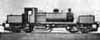
I have just had a bit of time away and, between doing some munro bagging, I took a little project to keep me occupied (and one has to plan for rainy days when you visit the highlands!).
I had finished the body of a Jones Goods a few years back, but it had a sticking chassis so had been put to one side. The peace and quiet without the family proved to be the opportunity to rebuild the chassis and get it running smoothly - this I managed after a certain amount of trial and tribulation (in part due to finding that at least some of the sticking was in fact a rough portescap!).
Add to this a few good munros (the Beinn Dearg group in particular was a really grand walk for those that are into these!), some field research and I feel I have had a successful time away!
There are a few bits still left to do and it is undoubtedly going to need to visit by the grit gun but it will soon be finished. Its origins are Jidenco - but as those that have built much of their work already know, that means that a good 40% is in fact scratchbuilt; in my case the running plate, cab, cab roof, cylinders, coupling & connecting rods, chunks of the tender and a lot of the detailing.
It was the fist time I used the High Level hornblocks - nice aren't they?
You do not have the required permissions to view the files attached to this post.
Mark Tatlow
-
Andy W
- Posts: 884
- Joined: Thu May 21, 2009 8:11 am
Re: A Highland Miscellany
Nice work Mark. A lovely engine.
Make Worcestershire great again.
Build a wall along the Herefordshire border and make them pay for it.
Build a wall along the Herefordshire border and make them pay for it.
-
Mark Tatlow
- Posts: 899
- Joined: Tue Dec 02, 2008 11:24 pm
Re: A Highland Miscellany
Ealing wrote:Nice work Mark. A lovely engine.
Thanks, Ealing; it is odd to think that they were the most powerful and the largest locomotives of their day anywhere, but when you put them side by side with a BR standard, they look like an anorexic!!
I have not managed that much modelling over the summer (shame!) and quite a lot of what has been done to the Big Goods is caught up under the chassis. However, I did get a backhead scratchbuilt (another component from the Jidenco kit that need not be bothered with.......). not too bad for something that is 15mm high!
The list of things to do is now beginning to get short; there is a real danger i might finish this one soon!
You do not have the required permissions to view the files attached to this post.
Mark Tatlow
-
Mark Tatlow
- Posts: 899
- Joined: Tue Dec 02, 2008 11:24 pm
Re: A Highland Miscellany
Only a little has been completed to the Big Goods this week; I was a little distracted by Portskerra at Woking (a very atmospheric layout I thought) and also by my trying my hand at some 3D CAD modelling.
In this case, I was trying my hand at a Highland Railway water column and here are the present results:
There are errors in what I have drawn, I think; so it will probably need redoing but i have found that the first one took about seven hours, the redrafting of it about three and I suspect that once I get going it will take less than two! It is Bill Bedford that alerted me to the moderate simplicity of this; although even though I was OK with CAD in 2D, the third dimension does take a lot of getting into. Hence the learning curve.
The idea will be to use the model to get a rapid prototype made of this CAD model, and then use this to make resin cast repeats. For those of you that are going to Scaleforum (if not why not!?!?) then I do urge you to look at Bill's stand - he has got some exquisit prototypes on show, including a MR Kirtly outside framed 0-6-0. I am quite sure that this is one area that the hobby will go down in the coming years.
You do not have the required permissions to view the files attached to this post.
Mark Tatlow
-
Mark Tatlow
- Posts: 899
- Joined: Tue Dec 02, 2008 11:24 pm
Re: A Highland Miscellany
To do something that will get itself finished fairly fast, I have picked up on some sheep vans. In this case these were designed by David Jones and are very characteristic of the Highland Railway, being two storeys high. I am not aware of any other company in the UK that used them - but I think the Irish may have - just an example of the economics of running a line on a shoestring!
These are based on a kit from Peter K, which are still available (or at least the etches are). They do need a lot of work though. Each of the bars has to be inserted individually and then there are multiple layers to build up to form the body, the sliding doors, the runners, the runner wheels, the end ribs and then the ironwork......................... They all then need fettling and tidying up to look smart. I reckon each of these represents around 15 -20 hours to the point that they can be painted, which I think is a little extreme for a wagon kit.
I have built one of these before and something I did not bargain on is how many sheep they can absorb - it is 38 on my first one!! I need to buy some good ones and then I will do blobs of filler on little legs for those at the centre of the floor.........
You do not have the required permissions to view the files attached to this post.
Mark Tatlow
-
Mark Tatlow
- Posts: 899
- Joined: Tue Dec 02, 2008 11:24 pm
Re: A Highland Miscellany
The two double deck sheep van are now finished (and given how much effort they took, an "at last" is not unwarrated!).
Here they are just starting their trip through the paint shop. One will be in HR livery (which is an umber but I think it will have faded lighter) and the other LMS grey. This is explains why there are different number of plated sections on the upper sides - two for the H and R, three for L, M and S.
I have also knocked up a couple of timber wagons. In contrast to the sheep vans, these went together in a couple of hours - they being white metall kits from Model Wagon Co. They are also for the paint shop:
I will load this with logs. I have used heather stems as logs in the past and will look to do so again. You can probably see the small holes in the side - on the kit this had a cast on O ring that ropes would have been tied too. I have removed these and will insert O rings with cord between them once the load are in.
You do not have the required permissions to view the files attached to this post.
Mark Tatlow
-
Mark Tatlow
- Posts: 899
- Joined: Tue Dec 02, 2008 11:24 pm
Re: A Highland Miscellany
Whilst I had lots of modelling plans for the Christmas break, the only one that really got off the ground was to experiment with servos for the operation of turnouts (TOUs) and signals. In this regard, my Christmas has been similar to
Firstly, dealing with turnout operation, I have made up a couple of mounts to support both the servo and mount a microswitch that will be used to operate the changing of the crossing polarity. The first prototype shows how it works a little better than the second prototype, as all is visible in the same shot.
However, prototype no 2 is much neater as it is a great deal more compact.
I plan to work on these a little more to refine them further, in part by producing a baseplate. This will be permanently secured to the underside of the layout and the actual TOU will be bolted to this. I aim to standardise the sizes of these and batch produce them (probably with an etch) so that if I do have a failure, it is a fairly simple matter of swapping over the servo and its TOU even in exhibition environs.
For some time I have moved away from tie bars that are part of the TOU; I had several problems with them including finding that they were sloppy as the heat from the soldering of connections to the switch rails distorted the plastic insulation material that held the support prongs and also because they did not hold the switch tightly against the stock rail. The old trick of a copper clad sleeper always seemed to me to be the most reliable but ugliest solution to this problem – thus I adopted this solution but buried the sleeper in the formation by utilising spacers of square section brass.
Hopefully the pictures show how this is put together and the final one shows that the whole of the gubbins can be hidden below paper which in turn receives the ballast on top. I have used these on Portchullin for several years now and the only problem that I have encountered is that I put mine in a routed slot that was not full depth, so I have had an accumulation of gunk get caught below them. Next time, I will route the slot to the full depth so that any dirt that gets through the paper (it has to have small slots for the arms that are soldered to the switches) just falls away.
I know the purist will say that the stress on the soldered joint between the tie bar and the switch rail will lead to the solder joint fracturing but I think the switch rail is just too flexible for this. I have not had any failures at this joint and my experience of almost all other layouts which use more delicate (hey I admit it refined!) tie bars do have quire regular failures here. So I am sticking!
You do not have the required permissions to view the files attached to this post.
Mark Tatlow
-
steamraiser
- Posts: 561
- Joined: Thu Dec 31, 2009 4:49 pm
Re: A Highland Miscellany
Mark,
My method is to turn the thin paxolin on edge and connect to the switch blade with apiece of 10 thou guitar string. This gives flexibility with ease of adjustment. If the paxolin is a light fit under to stock rails it will prevent the switch blades from rising.
Gordon A
Bristol
My method is to turn the thin paxolin on edge and connect to the switch blade with apiece of 10 thou guitar string. This gives flexibility with ease of adjustment. If the paxolin is a light fit under to stock rails it will prevent the switch blades from rising.
Gordon A
Bristol
-
barhamd

- Posts: 290
- Joined: Sun Jul 20, 2008 2:45 pm
Re: A Highland Miscellany
Hi Mark
This is interesting because I tried to use a very similar method for my first attempts with servos over the week. I found that the long operating wire pivots on the servo wouldn't give me enough torque to hold the blades over. This is wire I opted to build a separate TOU and then drive it from hole in the servo lever nearest the centre to get the torque I needed. I guess I may have had one (or all) of the following problems.
turnout blades too stiff to move or sprung unevenly
servo with no enough umph
too much friction somewhere in the design.
Any way, glad this worked for you...
David (Fen End Pit)
-
Terry Bendall
- Forum Team
- Posts: 2428
- Joined: Sun Jul 27, 2008 7:46 am
Re: A Highland Miscellany
Mark Tatlow wrote:The old trick of a copper clad sleeper always seemed to me to be the most reliable but ugliest solution to this problem – thus I adopted this solution but buried the sleeper in the formation by utilising spacers of square section brass.
A neat idea Mark. I notice that the example that you have posted is used with rails soldered to rivets. How do you think it would work with an Exactoscale turnout and plastic sleepers/chairs?
Terry Bendall
-
Mark Tatlow
- Posts: 899
- Joined: Tue Dec 02, 2008 11:24 pm
Re: A Highland Miscellany
Terry Bendall wrote:A neat idea Mark. I notice that the example that you have posted is used with rails soldered to rivets. How do you think it would work with an Exactoscale turnout and plastic sleepers/chairs?
Terry Bendall
I have not yet tried it but will do so this weekend probably.
I suspect the risk is that lingering with the soldering iron will melt the adjacent slide chairs so it is merely a question of moving fast. I guess if i were clever, I would have left off the adjacent couple of slide chairs until after the soldering but then I am not clever!
Mark Tatlow
-
Mark Tatlow
- Posts: 899
- Joined: Tue Dec 02, 2008 11:24 pm
Re: A Highland Miscellany
barhamd wrote:Hi Mark
This is interesting because I tried to use a very similar method for my first attempts with servos over the week. I found that the long operating wire pivots on the servo wouldn't give me enough torque to hold the blades over. This is wire I opted to build a separate TOU and then drive it from hole in the servo lever nearest the centre to get the torque I needed. I guess I may have had one (or all) of the following problems.
turnout blades too stiff to move or sprung unevenly
servo with no enough umph
too much friction somewhere in the design.
Any way, glad this worked for you...
David (Fen End Pit)
I am using the Tower Pro SG90s which are the same as you I think?
I have not had any problems with the blades not being inclined to move or being held over - I hope it is not just that I am lucky on the couple that I have done though! Time will tell I guess.
Keith Norgrove has used them quite extensively and for some time, so when he sees this posting perhaps he can comment?
Mark Tatlow
-
grovenor-2685

- Forum Team
- Posts: 3923
- Joined: Sun Jun 29, 2008 8:02 pm
Re: A Highland Miscellany
Although I build mine on Exactoscale tortoise adapters I use exactly the same principle Mark has used. The spring wire has to be strong enough to throw the points and IMHO its best to use as much of the throw of the servo as possible so the pivot for the spring wire should be much nearer the tie bar than the servo horn to give the leverage. If the servo is not producing enough torque to move a set of points then I think you should look at the points to see why they are so hard to move. Many of my servos are operating both ends of crossovers from one servo without any difficulty. Although I have not yet used an SG90 in that mode I don't see it being a problem.
Regards
Keith
Regards
Keith
-
barhamd
- Posts: 290
- Joined: Sun Jul 20, 2008 2:45 pm
Re: A Highland Miscellany
I realised looking at what you Mark had done that I had missed using a pivot on the wire from the servo, I was just extending the arm from the servo and expecting that to work. Obviously if you pivot the wire you can get an additional mechanical advantage. I'll leave the ones that i have build using a separate TOU and servo holder (see http://www.rmweb.co.uk/community/index.php?/blog/186/entry-8275-fitting-tous) but try this method next time.
thanks
David
thanks
David
Who is online
Users browsing this forum: ClaudeBot and 0 guests