Brimsdown-The last grand project.

Tell us about your layout, where you put it, how you built it, how you operate it.
User avatar
Le Corbusier
Posts: 1600
Joined: Wed Feb 11, 2015 3:39 pm

Re: Brimsdown-The last grand project.

Postby Le Corbusier » Sun Feb 04, 2018 9:01 am

Tim Lee

petermeyer
Posts: 312
Joined: Tue Oct 01, 2013 10:06 am

Re: Brimsdown-The last grand project.

Postby petermeyer » Sun Feb 04, 2018 11:28 am

Martin Wynne wrote:

...However, if the check rail and wheelset are not ... etc, etc, having a radius to the knuckle is helpful for traffic in the trailing direction, and potentially harmful for traffic in the facing direction.

But the worst condition of all is a sharp knuckle bend which is not exactly aligned. A radiused knuckle has a bit more leeway in positioning before the real grief begins:


Thanks Martin,

Last year I bought a mint gauge at S4rum North and on checking found all 6 of my crossings to be tight in this location. My track is riveted so I made some adjustments and a did little filing and things have improved. I was concerned that I may have undone a fundamental in doing this but you have put my mind to rest. I am less concerned with the aesthetics rather than good running. But as you can see from the attached shot, a little filing is not un-prototypical (though this is probably wear). Beware though this photo was taken at the site of the Ditton Junction disaster in 1912 on the LNWR!

Crossings_1912_Lnwr.jpg


NB: the track was deemed not to blame for the accident
You do not have the required permissions to view the files attached to this post.

User avatar
Paul Townsend
Posts: 964
Joined: Mon Sep 14, 2009 6:09 pm

Re: Brimsdown-The last grand project.

Postby Paul Townsend » Sun Feb 04, 2018 12:57 pm

petermeyer wrote:Thanks for clearing this up. How would one go about correcting the mis-built wing rails, following the previous advice, without resorting to a complete rebuild? Would filing suffice?
Peter


If it ain't broke, don't fix it!

My wing knuckles are sharpish bends and very rarely are implicated in derailments. When they do its usually hot mid-summer since Highbridge moved home and gets temperature swings that it didn't used to feel. Then the flangeway gauge doesn't go into the gap. A tickle with a file cures that.

User avatar
Martin Wynne
Posts: 1172
Joined: Mon May 14, 2012 4:27 pm

Re: Brimsdown-The last grand project.

Postby Martin Wynne » Sun Feb 04, 2018 4:14 pm

petermeyer wrote:But as you can see from the attached shot, a little filing is not un-prototypical (though this is probably wear). Beware though this photo was taken at the site of the Ditton Junction disaster in 1912 on the LNWR!
Crossings_1912_Lnwr.jpg

Hi Peter,

Many thanks for that photo. Clearly there is something amiss with the rail alignments to get that degree of side wear at the knuckle. On a model of course you would get a derailment rather than wear.

If we take the MR drawing which I posted earlier at face value this is what you get:

wrong_knuckle.png

If the knuckle is radiused, as it must be in practice if it is made by bending rail, and you then bolt it up to the same knuckle gap as the flangeway gap, the rails will be out of alignment with the vee. As shown by the red lines. I suspect that is what is happening in your photo.

The blue shows a correctly aligned knuckle -- the knuckle radius there is set to match GWR practice (unit angle in feet), and the kuckle gap is wider than the flangeway gap.

I suspect this is also the problem in model crossings when folks have trouble. The bend can't physically be made dead sharp. So if you then assemble it with the knuckle gap tight to the crossing flangeway gauge, the rails are bound to be out of line with the vee. Even if the bend has been made unnecessarily as sharp as possible, it should still be assembled so that the flangeway gauge is a loose fit in the knuckle gap.

cheers,

Martin.
You do not have the required permissions to view the files attached to this post.
40+ years developing Templot. Enjoy using Templot? Join Templot Club. Be a Templot supporter.

Tony Wilkins
Posts: 818
Joined: Tue Mar 20, 2012 3:57 pm

Re: Brimsdown-The last grand project.

Postby Tony Wilkins » Sun Feb 04, 2018 6:22 pm

Martin Wynne wrote:
Apologies to Tony that we seem to be drifting away from his project, although he started this knuckle bend business. Image

cheers,

Martin.


Hi Martin.
No need to apologise. All interesting and useful stuff.
Thoroughly explained to boot.
If it helps to raise awareness of the issue then that is all to the good, for which I make no apologies.
One of the things I do after I construct a crossing vee is to lay the Crossing Flangeway gauge on its side in the flangeway and slide it toward the knuckle. It should slide gently past the bend in line with the Wing rail. If it hits the corner of the wing rail bend, you have a problem and the wing rails needs adjusting.
EDIT to illustrate.
DSCF0478.JPG

The CF gauge should be a good sliding fit, near enough vertical.
DSCF0479.JPG

Here the CF gauge should be a loose fit, you can see that it is leaning over. At the very least it should go in effortlessly.
DSCF0480.JPG

Checking the alignment through the Vee.
DSCF0481.JPG

Same for the other road.


Regards
Tony.
You do not have the required permissions to view the files attached to this post.
Inspiration from the past. Dreams for the future.

Terry Bendall
Forum Team
Posts: 2426
Joined: Sun Jul 27, 2008 7:46 am

Re: Brimsdown-The last grand project.

Postby Terry Bendall » Mon Feb 05, 2018 9:04 am

Tony Wilkins wrote:Checking the alignment through the Vee.


My take on this test is to use a thin 150mm long steel rule. The one I have is the correct thickness and is useful for checking that you have either a smooth curve or a straight path through the crossing. Another good test is to hold the turnout up and look down it. The Mk. one eyeball is a very good checking tool. :) When everything is assembled the Roger Sanders gauge, sometimes called the mint gauge, is also useful for checking the you have a smooth path through the crossing.

Terry Bendall

User avatar
Le Corbusier
Posts: 1600
Joined: Wed Feb 11, 2015 3:39 pm

Re: Brimsdown-The last grand project.

Postby Le Corbusier » Mon Feb 05, 2018 9:10 am

Tony Wilkins wrote:
Martin Wynne wrote:
Apologies to Tony that we seem to be drifting away from his project, although he started this knuckle bend business. Image

cheers,

Martin.


Hi Martin.
No need to apologise. All interesting and useful stuff.
Thoroughly explained to boot.
If it helps to raise awareness of the issue then that is all to the good, for which I make no apologies.
One of the things I do after I construct a crossing vee is to lay the Crossing Flangeway gauge on its side in the flangeway and slide it toward the knuckle. It should slide gently past the bend in line with the Wing rail. If it hits the corner of the wing rail bend, you have a problem and the wing rails needs adjusting.
EDIT to illustrate.
DSCF0478.JPG
The CF gauge should be a good sliding fit, near enough vertical.
DSCF0479.JPG
Here the CF gauge should be a loose fit, you can see that it is leaning over. At the very least it should go in effortlessly.
DSCF0480.JPG
Checking the alignment through the Vee.
DSCF0481.JPG
Same for the other road.


Regards
Tony.

That is interesting Tony. Maybe I have been constructing my crossings incorrectly but I have been using my gauges (I have two) lengthwise to set up and solder things into position from the off ... the reasoning being that I wanted to ensure a straight run through and past the knuckle with what I assumed was the correct clearance. I have never used the gauge vertically. Anyway, everything appears to work.
Tim Lee

User avatar
grovenor-2685
Forum Team
Posts: 3921
Joined: Sun Jun 29, 2008 8:02 pm

Re: Brimsdown-The last grand project.

Postby grovenor-2685 » Mon Feb 05, 2018 10:50 am

Maybe I have been constructing my crossings incorrectly

Not incorrect, that is a perfectly good method, you can also use a track gauge as part of the check.
Image
The wing rail is held in place by track gauges and a crossing flangeway gauge and soldered. Use the steel rule, or a block gauge if you have one to confirm that the alignment from wing to nose is straight, take it off and repeat if any error found as alignment here is important for good running.

Regards
Regards
Keith
Grovenor Sidings

Tony Wilkins
Posts: 818
Joined: Tue Mar 20, 2012 3:57 pm

Re: Brimsdown-The last grand project.

Postby Tony Wilkins » Mon Feb 05, 2018 1:29 pm

Hi guys. I learnt long ago that there is more than one way to skin a cat.
Keith starts with the straight stock rail as a reference and for a single turnout this is likely to be fine. I never do, always positioning the crossing Vees first and working outwards. The reason for this is that with more complex pieces such as a Tandem starting with either stock rail and working across, cumulative errors can become appreciable by the time one reaches the far stock rail. Starting from a more central position keeps these issues to a minimum especially important where accurate rivet positions are required.
I did use to look along the rail to detect any misalignment, but age and a receding near point have put paid to that now.
Regards
Tony.
Inspiration from the past. Dreams for the future.

User avatar
Martin Wynne
Posts: 1172
Joined: Mon May 14, 2012 4:27 pm

Re: Brimsdown-The last grand project.

Postby Martin Wynne » Mon Feb 05, 2018 2:31 pm

Tony Wilkins wrote:I did used to look along the rail to detect any misalignment, but age and a receding near point have put paid to that now.

I still remember the day I lifted the work board to my eye to look along the rail. An unnoticed pointed needle file slid along the rail towards my eye. I just managed to avoid it. Lessons are always learned the hard way. Ever afterwards I have turned something upside down before lifting it to my eye, even paper templates.

regards,

Martin.
40+ years developing Templot. Enjoy using Templot? Join Templot Club. Be a Templot supporter.

JFS
Posts: 813
Joined: Wed Dec 16, 2009 3:47 pm

Re: Brimsdown-The last grand project.

Postby JFS » Mon Feb 05, 2018 3:46 pm

Martin Wynne wrote:
Tony Wilkins wrote:I did used to look along the rail to detect any misalignment, but age and a receding near point have put paid to that now.

I still remember the day I lifted the work board to my eye to look along the rail. An unnoticed pointed needle file slid along the rail towards my eye. I just managed to avoid it. Lessons are always learned the hard way. Ever afterwards I have turned something upside down before lifting it to my eye, even paper templates.

regards,

Martin.


I am sure neither of you chaps need this tip from me, but for those who don't know, a small mirror can help in both these matters! And for anyone like me, who builds their track in-situ, it is a must!

Best wishes,

User avatar
Martin Wynne
Posts: 1172
Joined: Mon May 14, 2012 4:27 pm

Re: Brimsdown-The last grand project.

Postby Martin Wynne » Mon Feb 05, 2018 4:11 pm

JFS wrote:I am sure neither of you chaps need this tip from me, but for those who don't know, a small mirror can help in both these matters! And for anyone like me, who builds their track in-situ, it is a must!

A mirror is great for straight rails. Also the lightest grade of nylon fishing line, stretched between blobs of Blue-Tack.

But for eyeing-in a curve, you can't beat an eye. The clue is in the name. Image

Martin.
40+ years developing Templot. Enjoy using Templot? Join Templot Club. Be a Templot supporter.

User avatar
Le Corbusier
Posts: 1600
Joined: Wed Feb 11, 2015 3:39 pm

Re: Brimsdown-The last grand project.

Postby Le Corbusier » Mon Feb 05, 2018 4:43 pm

JFS wrote:
I am sure neither of you chaps need this tip from me, but for those who don't know, a small mirror can help in both these matters! And for anyone like me, who builds their track in-situ, it is a must!

Best wishes,


Light bulb moment ... thanks Howard :thumb
Tim Lee

User avatar
Paul Townsend
Posts: 964
Joined: Mon Sep 14, 2009 6:09 pm

Re: Brimsdown-The last grand project.

Postby Paul Townsend » Mon Feb 05, 2018 7:01 pm

Le Corbusier wrote:
JFS wrote:
I am sure neither of you chaps need this tip from me, but for those who don't know, a small mirror can help in both these matters! And for anyone like me, who builds their track in-situ, it is a must!

Best wishes,


Light bulb moment ... thanks Howard :thumb


Yes to the mirror here too...a great help. I can still manage with a flat one but there is a case for a curved one if your sight focussing has deteriorated. Unfortunately, AFAIK you cant but convex ones, only concave like dental mirrors.

Tony Wilkins
Posts: 818
Joined: Tue Mar 20, 2012 3:57 pm

Re: Brimsdown-The last grand project.

Postby Tony Wilkins » Mon Feb 05, 2018 11:32 pm

I used to have a small rectangular ex-makeup mirror in my tool kit for just that purpose until I opened the toolbox one day to find it in several pieces. I never got round to replacing it.
I think you may find that some car mirrors are convex, particularly the drivers door mirror..
Regards
Tony.
Inspiration from the past. Dreams for the future.

petermeyer
Posts: 312
Joined: Tue Oct 01, 2013 10:06 am

Re: Brimsdown-The last grand project.

Postby petermeyer » Tue Feb 06, 2018 8:44 am

Thanks all for your helpful comments on the subject of crossings and knuckles which have been most enlightening. I too have two crossing flangeway gauges. One is an original Studiolith the other I think from the EM Gauge Soc. though I no longer know which is which. Last night I checked them and found one to be .68 the other .75! This might go some way to explain my running problems. Rather than hijack this thread further I should probably start my own thread.

Peter

Tony Wilkins
Posts: 818
Joined: Tue Mar 20, 2012 3:57 pm

Re: Brimsdown-The last grand project.

Postby Tony Wilkins » Tue Feb 06, 2018 1:38 pm

Hi Peter.
That could indeed explain a lot.
The 0.68mm one will be the Studiolith one. The 0.75mm one must be the new EM standard. Puts on tin hat!
Seriously though, I am glad that this diversion from the main topic, which I feely admit that I started, has proven useful.
I do intend to start a series of separate threads covering different aspects of P&C (Point and Crossing) work at some stage and some of this thread would really be more appropriate there.
Hope to get back on topic later, if I can remember where I got to.
Regards
Tony.
Inspiration from the past. Dreams for the future.

User avatar
Julian Roberts
Posts: 1393
Joined: Sat Jan 09, 2010 11:33 pm

Re: Brimsdown-The last grand project.

Postby Julian Roberts » Tue Feb 06, 2018 3:04 pm

Tony I think my request may have been to blame for starting this diversion; in any case I'm pleased you are thinking of covering these things in more detail in a separate thread. I will be interested in how you make the crossing without reference to any stock rail. On my limited experience so far I found it difficult to judge how far from the crossing nose the knuckle should be. Starting with a pre-bent knuckle to the correct angle, and the assumption that the route along the running rails and V must be straight (at least through a straight crossing), and the flangeway gap as given by the gauge, it was difficult to actually tell by feel where the precise place was where both were really in line. Photo below, a 1:8 angle. The flatter the crossing angle (i.e the bigger the number) the more difficult I would find it.

Looking at Martin's table on P2 of this thread, for example the distance on a 1 in 12 crossing is shown as 702mm. Scaled down that's 9.2mm, which looking at your C12 point on P1 looks as though may be what you have. To know the distance makes things easier - though I suppose that then makes the exact amount of blunting of the V more critical.

Although I could make half the crossing as shown without reference to a diverging stock rail, I couldn't do the other wing/knuckle rail without gauging from the straight stock rail.

Anyway I don't want to further hijack/divert your thread, rather to "point" towards what I would be interested to know more about your approach when you come to it on the promised separate thread, though of course there is more than one way of skinning a cat. The other main issue I would be interested in is your manner of thinking about the blade tips. As you said in the same post as the C12 picture:

Note how the top level of the switch blade falls toward the tip to ensure a smooth take up of the wheel tread.
You do not have the required permissions to view the files attached to this post.

User avatar
Martin Wynne
Posts: 1172
Joined: Mon May 14, 2012 4:27 pm

Re: Brimsdown-The last grand project.

Postby Martin Wynne » Tue Feb 06, 2018 3:41 pm

Julian Roberts wrote:On my limited experience so far I found it difficult to judge how far from the crossing nose the knuckle should be.

Hi Julian,

The extent of the knuckle bend, and its centre, are marked across the gap on the Templot template:

Image

You could measure from the template. Also the FP intersection mark.

It's also possible to print a duplicate template on tracing paper (inkjet printer, not laser), which can be placed on top of the rails to check alignment.

regards,

Martin.
40+ years developing Templot. Enjoy using Templot? Join Templot Club. Be a Templot supporter.

User avatar
Julian Roberts
Posts: 1393
Joined: Sat Jan 09, 2010 11:33 pm

Re: Brimsdown-The last grand project.

Postby Julian Roberts » Tue Feb 06, 2018 3:59 pm

Thanks Martin. Sorry to say I have not explored the delights of Templot very far yet. ;)
I suppose I am coming from the idea of not fully trusting a drawing. I was using one given to me by our track boss that had become a bit dodgy, having been a bit mangled in the printing out and sticking down process. I was thinking that it might be as valuable to be trying to do it simply from gauges and straight edges. But yes the place marked on the drawing was in the right place and more easily seen. Do the distances in the table scale down correctly for us in P4?

User avatar
Martin Wynne
Posts: 1172
Joined: Mon May 14, 2012 4:27 pm

Re: Brimsdown-The last grand project.

Postby Martin Wynne » Tue Feb 06, 2018 4:26 pm

Julian Roberts wrote:Do the distances in the table scale down correctly for us in P4?

Hi Julian,

Which table? Generally prototype dimension can be scaled exactly for S4 (S4-X in Templot), but not always for P4. The knuckle for P4 will be further from the nose of the crossing. Add on the amount of extra flangeway multiplied by the crossing angle. The extra flangeway is 0.67mm-0.58mm = 0.09mm. So for a 1:8 crossing the knuckle will be 0.09 x 8 = 0.72mm further from the crossing in P4 than in S4.

regards,

Martin.
40+ years developing Templot. Enjoy using Templot? Join Templot Club. Be a Templot supporter.

User avatar
Martin Wynne
Posts: 1172
Joined: Mon May 14, 2012 4:27 pm

Re: Brimsdown-The last grand project.

Postby Martin Wynne » Tue Feb 06, 2018 4:30 pm

Martin Wynne wrote:
Julian Roberts wrote:Do the distances in the table scale down correctly for us in P4?

Hi Julian,

Which table? Generally prototype dimension can be scaled exactly for S4 (S4-X in Templot), but not always for P4. The knuckle for P4 will be further from the nose of the crossing. Add on the amount of extra flangeway multiplied by the crossing angle. The extra flangeway is 0.67mm-0.58mm = 0.09mm. So for a 1:8 crossing the knuckle will be 0.09 x 8 = 0.72mm further from the crossing in P4 than in S4.

regards,

Martin.
40+ years developing Templot. Enjoy using Templot? Join Templot Club. Be a Templot supporter.

User avatar
Julian Roberts
Posts: 1393
Joined: Sat Jan 09, 2010 11:33 pm

Re: Brimsdown-The last grand project.

Postby Julian Roberts » Tue Feb 06, 2018 4:51 pm

Thanks Martin. Thats clear. The table I meant is the REA one you put here on P3 (not P4 as I erroneously put earlier) on Feb 4 at 1244am.

Tony Wilkins
Posts: 818
Joined: Tue Mar 20, 2012 3:57 pm

Re: Brimsdown-The last grand project.

Postby Tony Wilkins » Tue Feb 06, 2018 5:14 pm

Julian Roberts wrote:Tony I think my request may have been to blame for starting this diversion; in any case I'm pleased you are thinking of covering these things in more detail in a separate thread. I will be interested in how you make the crossing without reference to any stock rail. On my limited experience so far I found it difficult to judge how far from the crossing nose the knuckle should be. Starting with a pre-bent knuckle to the correct angle, and the assumption that the route along the running rails and V must be straight (at least through a straight crossing), and the flangeway gap as given by the gauge, it was difficult to actually tell by feel where the precise place was where both were really in line. Photo below, a 1:8 angle. The flatter the crossing angle (i.e the bigger the number) the more difficult I would find it.

Anyway I don't want to further hijack/divert your thread, rather to "point" towards what I would be interested to know more about your approach when you come to it on the promised separate thread, though of course there is more than one way of skinning a cat. The other main issue I would be interested in is your manner of thinking about the blade tips. As you said in the same post as the C12 picture:

Note how the top level of the switch blade falls toward the tip to ensure a smooth take up of the wheel tread.


Hi Julian.
Only partly I think. The diversion re knuckles had already begun.
My thinking is that I will break down the turnout construction into three parts. Starting with the Vee, The switch-blades and putting it all together, which is roughly how I did my recent tutorial at NAG.
I have a B-6 1/2 to construct for Brimsdown (Bullhead rail) which will make an ideal subject, but don't want to repeat what will be in them here. I will explain it all in due course. I do have many pictures of some of the steps involved, but not enough of the fine detail. I would advise using Templot printouts as your guide to bend positions etc. as with a properly calibrated printout, the accuracy is such that one can almost build a Turnout to them without gauges, (Not recommended) but I have been known to accidentally solder the second rail in by eye following the drawing and then tried the gauge only to find it a good fit.
Regards
Tony.
Inspiration from the past. Dreams for the future.

Tony Wilkins
Posts: 818
Joined: Tue Mar 20, 2012 3:57 pm

Re: Brimsdown-The last grand project.

Postby Tony Wilkins » Tue Feb 06, 2018 6:18 pm

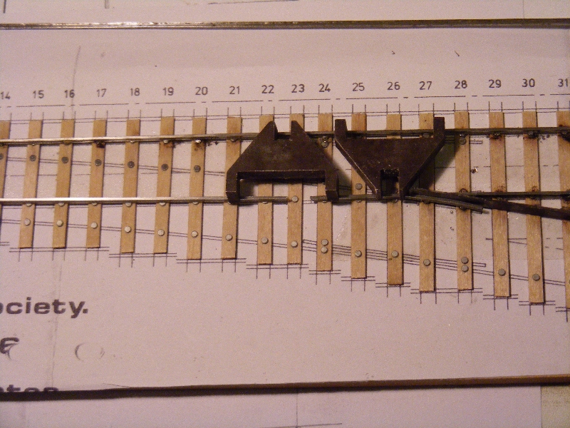
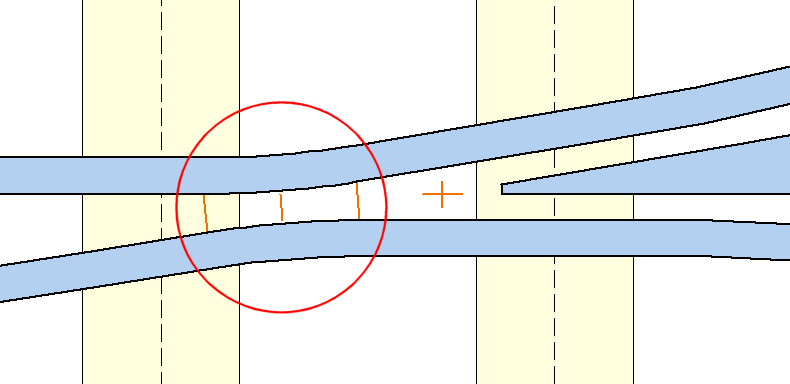
Going back to look at my first crossover for the layout in a bit more detail.

Xover 1.JPG

Compare with the real thing.
Brimsdown037.JPG

This photo was take on a cold frosty morning and really shows the timbers well.
Note how the timber ends on the left hand edge are more or less in line, whereas those to the right are most irregular. There is also some variation in the middle too. Something I have hopefully replicated on the model. There was another puzzle. When I first attempted to Templot this formation, I allowed increased track spacing because of the curvature, but this just did not work. There are only three timbers in the space between the ends of the wing rails of the two turnouts. This could only be achieved by reducing the track centres to standard spacing. Although this would not be allowed on a main line, I suspect that as this was only a one engine in steam area (typically a J15 or other small 0-6-0 for which the GER were so well known) and short wheelbase wagons were the majority of the traffic that there was sufficient clearance between the stock on each road. I have checked the result with a loco (in my case a BTH type 1, class 15) and wagon and it is not too bad, so don't assume the obvious is I suppose the moral here.
But why the odd timbering, which had me baffled for many years?
There is a clue in a 1938 map I recently discovered.
Brimsdown 1938.png

Note how the curving tracks at the bottom middle become single part way round the curve.
When I knew the area in the late 1960's the double track extended to somewhere near the right angle crossing at the top of the map and the engineering works had long gone. Indeed there was a new road running through the middle of where it once was.
I also have a 1947 LNER 40 foot to the inch map of the area and it was double track by then.
The conclusion is that due the the increased traffic demands of WW2, the single track was doubled with the new crossover installed from whatever materials were available. Incidentally from personal observation the crossover consisted of a left and right hand turnout rather than the usual arrangement.
Due to the severe curvature of the track at the bottom of the map, there was a sign prohibiting locos from proceeding much further than beyond the crossover to run round. It was about where the lane and foot path crosses the railway.
Regards
Tony.
You do not have the required permissions to view the files attached to this post.
Inspiration from the past. Dreams for the future.


Return to “Layouts and Operations”

Who is online

Users browsing this forum: ClaudeBot and 3 guests