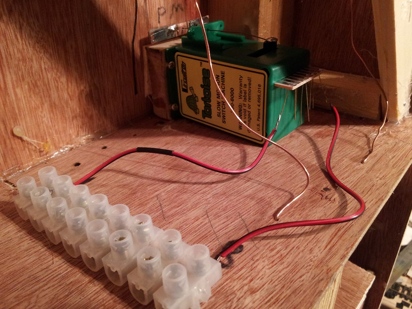
Knuckles wrote:What is scaring me the most is how to wire the Tortoise point motors. +,- and 1 auxilary to each frog?
Does this help.........http://www.scalefour.org/resources/tortoise-wiring.html

Knuckles wrote:What is scaring me the most is how to wire the Tortoise point motors. +,- and 1 auxilary to each frog?


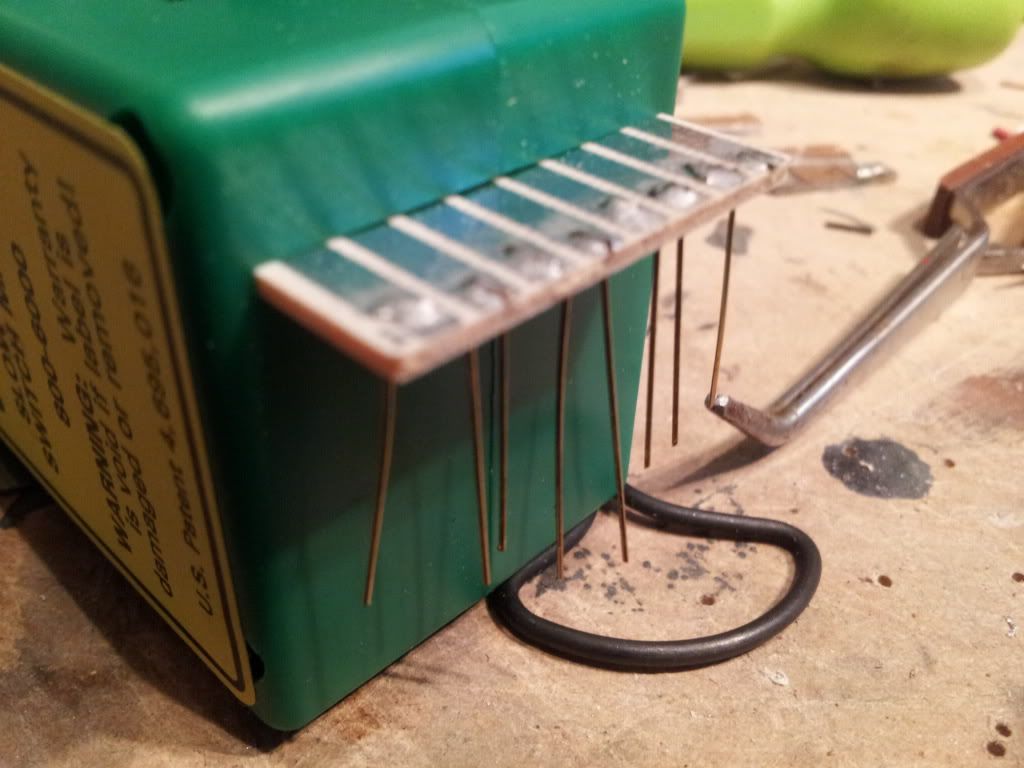
TEZBEDZ wrote:Russ, what would be the distance between the TOU tubes in your example?
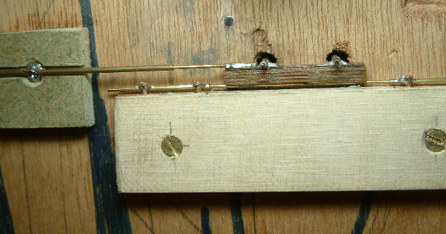
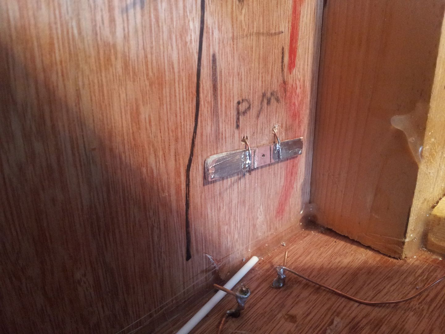
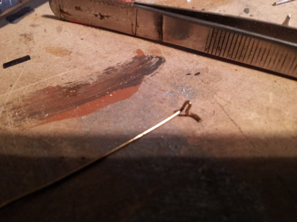
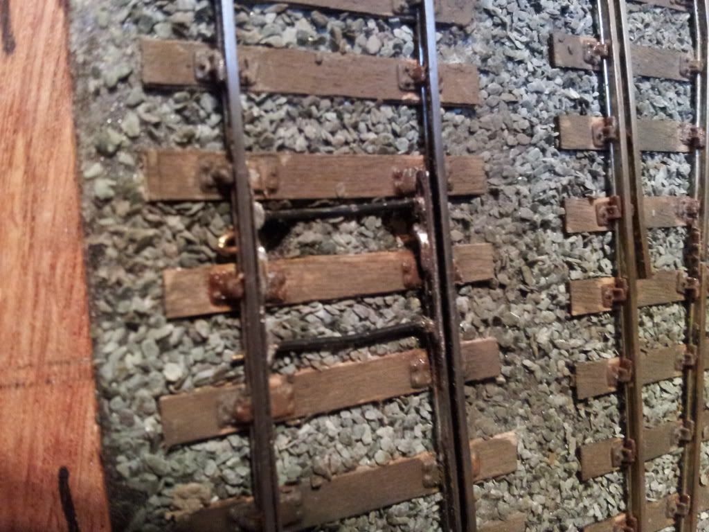
i would definitely recommend that you do not solder the bottom end of your point blade dropper to the underboard tie bar, much better to use a piece of tube as shown on the CLAG version, this takes the twisting stress out of the soldering and also stops any vertical movement of the underboard part affecting the blades above. So use dropper wires shaped as per Terry's diagram and fit tubes for the bottom end.
Am I correct in thinking that the idea of wrapping the droppers in plastic tub is so that the wire inside can wiggle and bend a 1/4 of a mm or so? I think that's what you are saying.
If so then I need to make dropers as I have but with a horizontal 'no lift' mech', and then instead of soldering the droppers to the tiebar underneith just wrap them in tubes and put those in friction fit holes in the tie bar. I think that's what your saying.
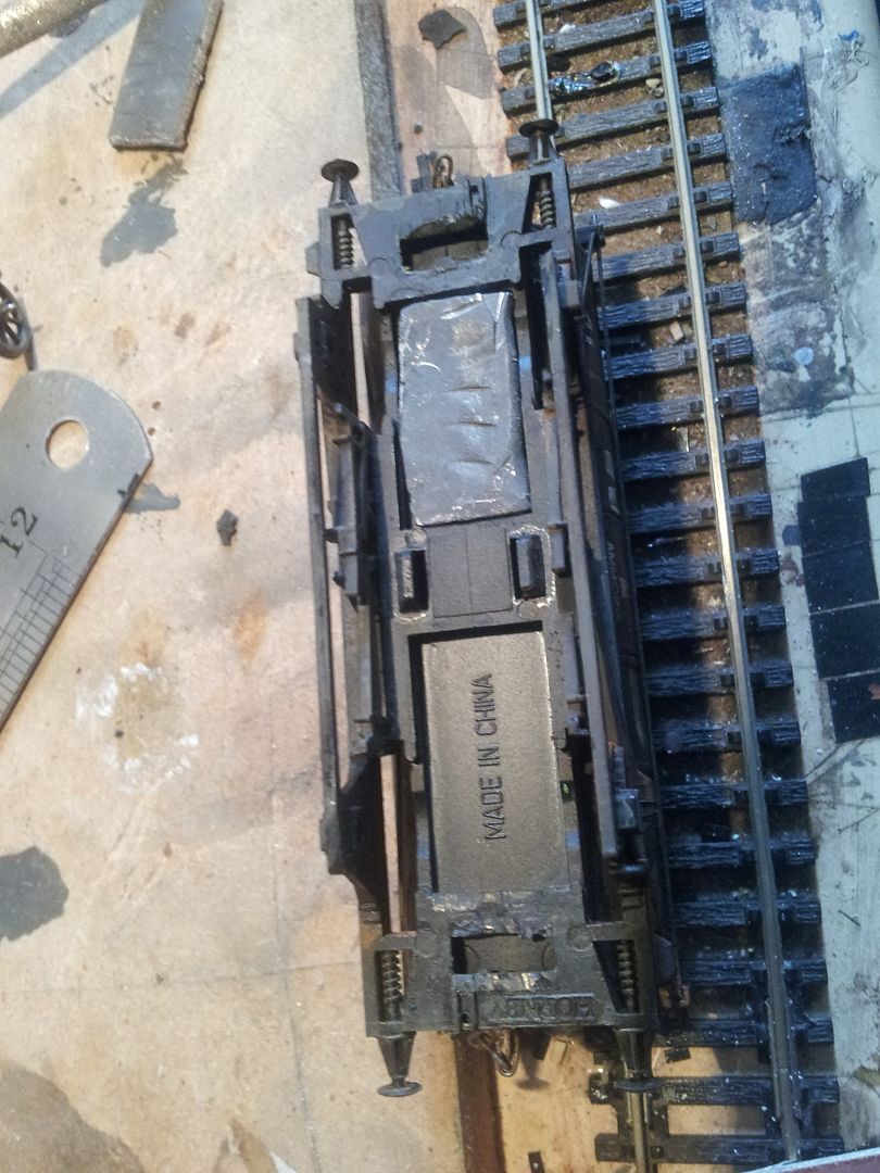
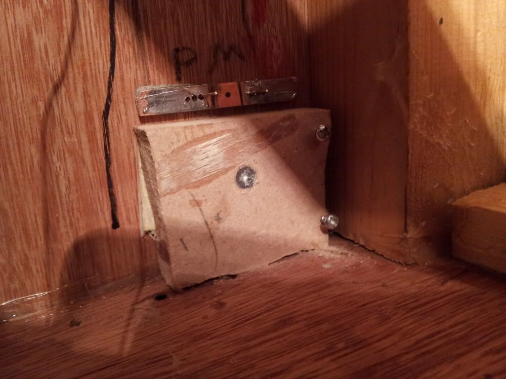
Would the Tortoise motor need to be on blocks to account for the tie bar being in the way or would you just mount it next to it and bend the operating wire 90degrees one way and then 90 the other again?
Do I even make sence!?
TEZBEDZ wrote:Russ, what would be the distance between the TOU tubes in your example?
allanferguson wrote:Russ's design, otherwise excellent, doesn't allow for the thickness of the swtchrail foot.
Return to “Layouts and Operations”
Users browsing this forum: ClaudeBot, SemrushBot and 2 guests