Why am I doing this? It's asking for trouble I know putting my dodgy efforts in front of you lot of craftsmen but I have a notion that the very act of documenting my progress, or otherwise, will keep me working. We shall see!
You may have heard a whisper that Burnham on Sea is being rescued from John Palmers attic and the target is completion for next years Railwells. Well these whispers have substance and I have the task of producing the signals. I'm working from sketches and measurements produced by John so I have little excuse for failure in the accuracy department apart from incompetence, and I am a passed master in that department.
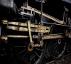
So here are the beginnings.
I am only the junior member of the group, albeit the oldest in years, so I feel I have to raise my game!
More anon.
Burnham Signals
-
stevecarr
Burnham Signals
You do not have the required permissions to view the files attached to this post.
-
DougN
- Posts: 1253
- Joined: Wed Sep 01, 2010 9:57 am
Re: Burnham Signals
Steve, well done! Posting on here does encourage more modelling. I have found signals difficult to fabricate as there are so many small parts. I must stop donating them to the floor gods! I think I will stick to loco's and rolling stock for a while to get things ready to run! then I can think more seriously about a layout and signals. Interesting to see that Burnham on sea is brought back. Was it not years ago in MRJ?
Doug
Still not doing enough modelling
Still not doing enough modelling
-
stevecarr
Re: Burnham Signals
Thanks Doug. I think posting work on here, knowing it will be viewed by members at large, will encourage me to avoid short cuts and the that will do mentality. Mind you,its a bit nerve racking!
As far as I know Burnham was never in MRJ but I could be wrong. I'll ask at todays VAG get together.
As far as I know Burnham was never in MRJ but I could be wrong. I'll ask at todays VAG get together.
-
Andy W

- Posts: 884
- Joined: Thu May 21, 2009 8:11 am
Re: Burnham Signals
Looking good Steve. Posting on here is definitely a positive thing.
Make Worcestershire great again.
Build a wall along the Herefordshire border and make them pay for it.
Build a wall along the Herefordshire border and make them pay for it.
-
DougN
- Posts: 1253
- Joined: Wed Sep 01, 2010 9:57 am
Re: Burnham Signals
My memory is getting rather long.... It could have been 2mm and in another mag  I think over the years I have read too many mags and the memory plays tricks at times! I'm interested in how you are driving them too! I think the servos seem to be the most efficient and cheapest wY to do this.
Doug
Still not doing enough modelling
Still not doing enough modelling
-
dal-t
- Posts: 654
- Joined: Mon Jan 11, 2010 8:06 pm
Re: Burnham Signals
Ah, I had the same feeling as Doug, and since the MRJ on-line index gave nothing, I was shaping up to sit down (yet again!) with all the old issues, despite the numerous modelling diversions that created last time. Fortunately (?) a quick wider search threw up the 2mm version (and, in a later issue, drawings of the station buildings) carried by a certain 'house' magazine that I no longer keep copies of.
It is always good to see signals being built, because they do seem to give an instant 'air' of the old railway, in a manner that little else does. I'm intrigued by that 'dangling' balance weight - was it a means of avoiding encroachment on the loading gauge in a restricted location? And (purely from interest, not being critical) is the angle of that unprimed ladder right - it looks as if it would give the 'elf and save tea crowd kittens these days.
It is always good to see signals being built, because they do seem to give an instant 'air' of the old railway, in a manner that little else does. I'm intrigued by that 'dangling' balance weight - was it a means of avoiding encroachment on the loading gauge in a restricted location? And (purely from interest, not being critical) is the angle of that unprimed ladder right - it looks as if it would give the 'elf and save tea crowd kittens these days.
David L-T
-
jim s-w

- Posts: 2190
- Joined: Wed Jul 30, 2008 5:56 pm
Re: Burnham Signals
stevecarr wrote:I am only the junior member of the group, albeit the oldest in years, so I feel I have to raise my game!
On the evidence posted here, if you feel that it's not by much.
Cheers
Jim
-
Tim V

- Posts: 2870
- Joined: Tue Jul 29, 2008 4:40 pm
Re: Burnham Signals
There was no article on the P4 Burnham. There are precious few photos as well!
I have tasked myself with writing something for the Snooze, but am hampered by a lack of photos of the model. The most comprehensive were taken 11 years ago on an inferior digital camera. Oh well, yet another challenge....
I have tasked myself with writing something for the Snooze, but am hampered by a lack of photos of the model. The most comprehensive were taken 11 years ago on an inferior digital camera. Oh well, yet another challenge....
Tim V
(Not all railways in Somerset went to Dorset)
(Not all railways in Somerset went to Dorset)
-
stevecarr
Re: Burnham Signals
David
I'm not sure of the reasoning behind the 'dangly weight' but they weren't uncommon. With regards to the ladder it's only resting there so as I know where it is! The signal will get a staging in due course.
Tim is right about the paucity of 'photo's for Burnham. I have been searching for views, detailed if poss, of the home bracket post but have only found two so far. If anyone out there can help we'd be very grateful.
Tim, can you look at picture number 8 on the Historic Burnam list? This doesn't seem to be Burnham - or is it the same post erected somewhere else?
Steve
-
stevecarr
Re: Burnham Signals
Doug,
I always use Servo's and will test the completed signals with them.
However, once in place on the layout, they will be driven by motors designed and built by the original Burnham team ie John P et al.
Regards
I always use Servo's and will test the completed signals with them.
However, once in place on the layout, they will be driven by motors designed and built by the original Burnham team ie John P et al.
Regards
-
Tim V
- Posts: 2870
- Joined: Tue Jul 29, 2008 4:40 pm
Re: Burnham Signals
Photo 8 was taken at Yieldingtree, the signals were moved to that museum.
Tim V
(Not all railways in Somerset went to Dorset)
(Not all railways in Somerset went to Dorset)
-
John Palmer
- Posts: 825
- Joined: Fri Jul 15, 2011 11:09 pm
Re: Burnham Signals
Steve, how good it is to see the first fruits of your endeavours on these signals, the more so since they authentically represent the Somerset & Dorset pattern of two rails closely bolted together!
Re the dangling balance weight: the photographic evidence does not suggest any likelihood of the lever being foul to gauge, the reason for it therefore remains open to speculation. My best guess is that it just ‘came to hand’, such was the diversity of components from which S&D signals were assembled (anyone care to speculate as to the origins of the pinnacles capping the Up Starting signal at Cole – LT&SR?).
At Railwells we touched upon the location of picture number 8 on the Historic Burnham list. I can now confirm that this is a picture taken by yours truly at the Yieldingtree Railway Museum, now long gone but located at Uphill station. This contained a collection of railway memorabilia assembled by Mr Bob Smallman that included one of the Burnham starters and the bracket signal mounting Up Main and Loop Home signals – more details in April 1968 edition of Railway World.
The museum’s exhibits were auctioned and dispersed in February 1968. Fortunately, the Burnham signals found their way to the S&D Railway Circle’s site at Radstock shed, and from thence were conveyed to Washford (at least in part) when the S&D Railway Museum Trust, as it had become, was forced to vacate Radstock in the 1970’s. Think I made some of the sketches to which Steve refers whilst the signals reposed in some elderly NCB mineral wagons retrieved to Radstock from Kilmersdon Colliery via its incline.
Steve, a word of warning: the pinnacle you see surmounting the bracketed wooden doll in Photograph 8 was mounted in that position by Mr Smallman – it was not present, so far as I am aware, in all the time the signal stood at Burnham post-Nationalisation. During all the times I saw it at Burnham that doll was devoid of any pinnacle ornamentation.
I would post a copy of the photo under discussion but for some reason it's not uploading.
Edited to add: Success after much reduction in size!
You do not have the required permissions to view the files attached to this post.
-
stevecarr
Re: Burnham Signals
Just an update - both in works grey.
Down starter on the left and the loop starter on the right.
Down starter on the left and the loop starter on the right.
You do not have the required permissions to view the files attached to this post.
-
stevecarr
Re: Burnham Signals
Getting there - it seems to have taken forever!
You do not have the required permissions to view the files attached to this post.
-
CDGFife

- Posts: 245
- Joined: Thu Feb 28, 2013 6:37 pm
Re: Burnham Signals
stevecarr wrote:Getting there - it seems to have taken forever!
But it's always nice to get there when they look this good Steve!
Cheers
Chris
-
Andy W
- Posts: 884
- Joined: Thu May 21, 2009 8:11 am
Re: Burnham Signals
Indeed, excellent. And love the sign! It could be paraphrased to "To you it may only be a hobby, but to me it's a sanctuary".
Make Worcestershire great again.
Build a wall along the Herefordshire border and make them pay for it.
Build a wall along the Herefordshire border and make them pay for it.
-
stevecarr
Re: Burnham Signals
Andy
The sign was a christmas present from my daughter .Is she trying to tell me something?
Regards
The sign was a christmas present from my daughter .Is she trying to tell me something?
Regards
-
John Palmer
- Posts: 825
- Joined: Fri Jul 15, 2011 11:09 pm
Re: Burnham Signals
I see balance levers and back blinders have yet to go on the homes. It’s not entirely clear whether the loop home carried such a blinder although I believe it did. The Up Main Home definitely did – it’s visible in one of our photographs and can also be seen in the rear view of the signal in Athill’s Picture History of the S&D, painted white.
Have you had any further thoughts about actuation? Our standard motor drives give choices of a rotary action split into two 180 degree phases or a reciprocating action with 1cm travel - take your pick!
-
stevecarr
Re: Burnham Signals
Hello John
Thanks for the comments - the black bracket is, of course, painting what I assumed the colour to be and not what it actually was!
The home signals do indeed still have some work to do but the end is in site.
Regarding actuation, I'm playing around with servos' but am not totally convinced as to their suitability - twitching etc. but I've still some work to do.
I think at some stage we will have to get together and make some decisions - maybe I can pay a visit with the signals on a day trip.
Regards
Steve.
-
Serjt-Dave
- Posts: 643
- Joined: Tue Oct 02, 2012 3:31 pm
Re: Burnham Signals
Frantic work Steve, well done.
All Best
Dave
All Best
Dave
-
John Palmer
- Posts: 825
- Joined: Fri Jul 15, 2011 11:09 pm
Re: Burnham Signals
These signals have now been planted and made operational. Here’s a composite shot to show the operating mechanism from both sides, for a single arm signal.
Signal baseplate soldered to brass tube, 19mm OD for a one-arm signal. Box section bored for bearing shells to carry 2mm dia. journal on which the operating crank pivots. Shoulders of the bearings fitted inside box section, part of one side of which has been cut away to provide jaws between which crank can be mounted. The box section is then mounted within the tube using 1mm brass wire ‘dowels’. The crank is cut from 1/16th” brass strip, bored for pivot journal, clamping plate journal and drive bar adjustment shoe. The shoe is cut from U section brass and slotted for lateral adjustment at any one of the five available clamping points on the long leg of the crank. Final drive rod clamp plate nipped up onto a steel journal passing through short leg of crank by means of 12BA nut and bolt; this enables clamp plate to pivot, to avoid putting a bend onto the rod drive to the balance weight lever mounted on the signal post above as the crank turns. The plate is here pivoted on the crank’s short leg 5mm from the crank pivot, whilst the snap popper on the adjustment shoe is, in this case, positioned 37mm from the pivot; this gears down the displacement of the clamping plate so that the 10mm nominal input movement from the drive bar connected to one of our standard drive motor units becomes the required 1.5 – 2mm output movement on the final rod drive to the signal.
Signal baseplate soldered to brass tube, 19mm OD for a one-arm signal. Box section bored for bearing shells to carry 2mm dia. journal on which the operating crank pivots. Shoulders of the bearings fitted inside box section, part of one side of which has been cut away to provide jaws between which crank can be mounted. The box section is then mounted within the tube using 1mm brass wire ‘dowels’. The crank is cut from 1/16th” brass strip, bored for pivot journal, clamping plate journal and drive bar adjustment shoe. The shoe is cut from U section brass and slotted for lateral adjustment at any one of the five available clamping points on the long leg of the crank. Final drive rod clamp plate nipped up onto a steel journal passing through short leg of crank by means of 12BA nut and bolt; this enables clamp plate to pivot, to avoid putting a bend onto the rod drive to the balance weight lever mounted on the signal post above as the crank turns. The plate is here pivoted on the crank’s short leg 5mm from the crank pivot, whilst the snap popper on the adjustment shoe is, in this case, positioned 37mm from the pivot; this gears down the displacement of the clamping plate so that the 10mm nominal input movement from the drive bar connected to one of our standard drive motor units becomes the required 1.5 – 2mm output movement on the final rod drive to the signal.
You do not have the required permissions to view the files attached to this post.
-
stevecarr
Re: Burnham Signals
Great stuff John / look foreward to seeing them working.
In France now for most of July / give my eyes a rest / hope lead poisoning came to nought.
Steve
In France now for most of July / give my eyes a rest / hope lead poisoning came to nought.
Steve
-
stevecarr
Re: Burnham Signals
Just to close this thread are some pictures of the installed signals at the Wells Exhibition. The really hard work of getting them working was done by the indefatigable John Palmer, who, along with Gordon, took the brunt of the preparation labours to get the layout up to exhibition standards.
I would like to take this opportunity to thank all of the group for allowing me to participate, all be it in a small way, in the ongoing restoration work to this marvellous piece of documentary modelling.
I would like to take this opportunity to thank all of the group for allowing me to participate, all be it in a small way, in the ongoing restoration work to this marvellous piece of documentary modelling.
You do not have the required permissions to view the files attached to this post.
Who is online
Users browsing this forum: ClaudeBot and 0 guests