Finishing the cylinder block and slide bars
Intrinsically I knew that the inside connecting rods would have some form of slide bars but my rather cursory glance around the GA and subsequent assumptions about how they would look and be fitted hit the buffers! Late in the day I realised that for each connecting rod there were four slide bars arranged in a square around the cross head. I was able to confirm this arrangement from another GA with similar inside cylinders and ‘deduce’ the possible shape not only for the cross head but also for the fitting block on the rear of the cylinder block.
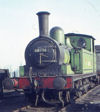
So the big question is, can anybody see any of this?
One of the delights of doing the drawing in 3D is that we can move the ‘camera’ around and view the model from all sorts of different angles and in this case, the answer is undeniably ‘yes’. Should I ever get around to doing the superheated version where the boiler is raised 4.5” then these parts will become much more visible.
Even if the motion is cosmetic, these parts have to be made.
These four slide bars are fitted into a rectangular box fitted to the rear of the cylinder block. The exact shape of this is a bit of a guess, again with the help of another GA. The rears of these slide bars fit into the frame spacer located just to the rear of the bogie. A stiffening plate has already been drawn on the inside of the frames but I have elected to put larger TABS on the spacer and fit these through both the stiffener and the frame. This will align both parts accurately.
The frame hangs below the level of the frames by several inches so is quite visible, it is also shaped. While the 1.25” NiSi we are using matches the thickness of the spacer, there are also beads around all the edges to strengthen this part. I suspect the frame is really quite weak in this area and needs all the help it can get.
The spacer also does not go to the top of the frames. There is a large diameter tube over the top of it which is used to create the vacuum for brakes etc. This needs some more research as to the exact position, but again I may have to make a deduction!
The spacer has two holes in it, the first is a simple rectangle around the slide bars. The second is a little more complex. This turns out to be an ellipse at an angle. The valve rod passes through the spacer but is guided by a tube which is welded to the spacer. The valve rod and tube are at an angle of 5.8 degrees as before and the requisite hole is made by copying the tube in place and subtracting the copy from the spacer.
Fire Box Bottom, motor and gear box fitting
The last major part to be designed is the fire box bottom, which I had previously referred to as the Ash Pan (thank you Arthur K for the clarification). I have made an assumption that it will look like most others I have seen and have lots of rivets. In this case the fire box bottom is much closer to the frames than my previous designs so it is spaced by a single layer of NiSi. The general shape was drawn as a polyline over the GA but then boxes and cylinders were drawn and added or subtracted to or from each to match the shape on the GA.
The thickness of this I have drawn as 0.56” or half the thickness of the NiSI sheet.
The rivets are drawn as cylinders and then “copy array” used to populate the whole area. Of course, the actual spacing is a little bit of a deduction – OK, it’s a guess.
Then the boring bit is simply to add all the rivets (cylinders) to the flat sheet to get the result shown.
At this point some readers will be wondering how such 3D parts can easily be translated into 2D etch layers. It is fairly straightforward but will be dealt with much later.
It was noted in an earlier post that a High Level Slimliner + could be used, but just to make sure, at this point I constructed a 3D model of the motor and a Mashima 1420 just to be certain. Since the motor overlaps the frames it was necessary just to make sure that it would fit and also that there was space for some lateral movement of the axle – which there is!
Genesis of a model locomotive design
-
John Bateson

- Posts: 809
- Joined: Wed Jul 02, 2008 6:39 pm
Re: Genesis of a model locomotive design
You do not have the required permissions to view the files attached to this post.
Last edited by John Bateson on Sat Dec 07, 2013 8:22 am, edited 1 time in total.
Slaving away still on GCR stuff ...
-
ArthurK
- Posts: 17
- Joined: Thu Oct 02, 2008 3:11 pm
Re: Genesis of a model locomotive design
Perhaps I am being a bit critical here but I think that you will find that the rivets are not on the ashpan but on the sides of the firebox bottom. The outer shell of the firebox was usually tied to the inner shell by a mesh of copper rivets roughly placed on a grid of about 3". The ashpan was a separate unit placed below the firebox firebars the collect the ash that fell through and normally had only a line of rivets at the bottom to hold an angle section along the base. Ashpans were usually steelsheets largely devoid of rivets.
The four slidebar arrangement was common on NER locos with inside cylinder (Tennant, R and W). But later the single slidebar became more common.
ArthurK
The four slidebar arrangement was common on NER locos with inside cylinder (Tennant, R and W). But later the single slidebar became more common.
ArthurK
NORTHEASTERN KITS
http://www.rmweb.co.uk/community/index. ... tern-kits/
Arthur's Workshop
http://www.rmweb.co.uk/community/index. ... -workshop/
http://www.rmweb.co.uk/community/index. ... tern-kits/
Arthur's Workshop
http://www.rmweb.co.uk/community/index. ... -workshop/
-
John Bateson
- Posts: 809
- Joined: Wed Jul 02, 2008 6:39 pm
Re: Genesis of a model locomotive design
Arthur,
Thank you for the clarification - I should have been able to work that one out!
Text below has been amended.
John
Thank you for the clarification - I should have been able to work that one out!
Text below has been amended.
John
Slaving away still on GCR stuff ...
-
John Bateson
- Posts: 809
- Joined: Wed Jul 02, 2008 6:39 pm
Re: Genesis of a model locomotive design
NB
1420 won’t fit when inserted from underneath – need a 1220 or 1224
Brakes
The brakes are tricky to do and there are some pitfalls.
Ideally the brakes should be touching the wheels – just – but this will cause electrical shorts. Plastic brakes can prevent this but they are not especially durable and there are two very fragile points where they can break. A solution may be to use a metal back plate and 3D printed front plate and shoes.
However, before we can do that, the design work must be done. In this case a simple set of dimensions and an outline traced and drawn in 2D arcs, circles and lines is done on top of the GA. Initially I was thrown by the ‘stretch’ in the GA mentioned earlier when I could not get things to line up as expected.
The various segments making up the outlines may be joined by the ‘chain polyline’ command, just select the first segment, select another point on the same segment and if we are lucky and all the segments touch at some point, sets of arrows will appear offering a choice for the draughtsman as to the next section. For TurboCAD, this action leaves us with a closed polyline in addition to the original segments, which may be deleted.
Note that the shoes are drawn for the top half only, this may be mirror copied about the line from the wheel centre to the centre of the back plate if needed, although I have only done it for the 3D part.
Next, the 2D outlines are copied on top of themselves, and the original converted to a 3D object simply by specifying the width and material for the parts. Cylinders are created to make the holes where needed and these are subtracted from the 3D parts.
Once this is done the parts need to be placed at the right distance from the centre line of the engine, simply define the reference point on each part and then set the ‘Y’ dimension to the correct value.
The test that all the holes are complete is to render (colour) the parts and check that the holes are ‘white’. If this is not the case then there are some holes missing. Remember that the frame also needs a hole for the rod on which the brakes are hung. For these frames there is also a small back plate on the inside of the frames to help mount these.
You do not have the required permissions to view the files attached to this post.
Slaving away still on GCR stuff ...
-
Will L

- Posts: 2524
- Joined: Sun Jul 20, 2008 3:54 pm
Re: Genesis of a model locomotive design
John
Of late I've been worrying about aligning brake blocks with wheels rims. How can I get them prototypically close together given I've got a up to of 1mm vertical movement on the axle (.5 either side of the normal position) which is, I understand, not all that different from the amount of movement available on the prototype.
My conclusion is that, even assuming you can allow the two to touch, it is only possible if the pivot between brake block and break hanger is functional so the block can align itself to the wheel. Even then, while the prototype may work fine with the brake blocks gently rubbing on the wheel tyres I strongly suspect the model would be markedly less happy. This is one area when I think those who go for a fully rigid chassis have an advantage.
Will
-
John Bateson
- Posts: 809
- Joined: Wed Jul 02, 2008 6:39 pm
Re: Genesis of a model locomotive design
Will,
I agree that only a pivot for the brake blocks would solve this particular dilemna but I doubt that it would work in 4mm scale.
One possible option is to make the brake shoe only a 3D printed part, with the back plate made of NiSi. This way the builder can align things to suit his/her own ideas about spacing and clearance. The current 3D printed offerings are both back plate and shoe, pre-aligned.
John
Slaving away still on GCR stuff ...
-
John Bateson
- Posts: 809
- Joined: Wed Jul 02, 2008 6:39 pm
Re: Genesis of a model locomotive design
Brake Pull Rods and Vacuum Cylinder
The main pull rod is a simple rod which fits into the front cross piece and rear cross piece, strengthened by small brackets top and bottom. The rear bracket is slightly different in that it must hold the end of the rear pull rod and this is simply two small brackets extended beyond the rear of the cross piece. The rear brake pull is a rod and in this case it is simply flattened at the front with a small hammer to fit between the brackets. At the rear it has an adjustment bracket which is a piece of flat bar with three adjustment holes in it. It is welded (soldered) to the rod. Fine adjustment is done by nuts and cylinders surrounding the rod. Since this rod is 0.7 mm (2” equivalent) then adding the threads to make it work is probably a hair shirt too far.
The mechanism associated with the vacuum cylinder takes a little while to sort out. Normally this complex shape would have arms at each end which would sit either side or the rear pull rod and either side of the rod in the vacuum cylinder. Since this part is really a bit small then this is not possible, but for the part around the rear brake pull it is possible to half etch the inside and achieve the same result.
The main axle is 4.5” (1.5 mm equiv.), the attachment to the vacuum cylinder is 1.5” (0.5mm equiv.) and the bottom hole is 2” (0.7 mm equiv.).
The main axle is also right at the edge of this part and the original was welded to the axle. To achieve the same look on assembly on the etch layer a larger circle will be added around the centre hole and once soldered in place, simply filed down.
Finally, TABS and SLOTS are added to the side supports and the frame spacer to locate this part accurately.
You do not have the required permissions to view the files attached to this post.
Slaving away still on GCR stuff ...
-
David Knight
- Posts: 819
- Joined: Sun Jul 20, 2008 6:02 pm
Re: Genesis of a model locomotive design
John,
Do you plan to design the brake gear so it can be removable for maintenance? I'm thinking of the 'clip on clip off' style favoured by Chris Gibbon and Bill Bedford.
Cheers,
David
Do you plan to design the brake gear so it can be removable for maintenance? I'm thinking of the 'clip on clip off' style favoured by Chris Gibbon and Bill Bedford.
Cheers,
David
-
John Bateson
- Posts: 809
- Joined: Wed Jul 02, 2008 6:39 pm
Re: Genesis of a model locomotive design
When I think of how many times I take things apart after the first, second and third and subsequent fittings then removable brakes (and a few other parts) are mandatory.
In this case, a small length of tube soldered to the rear of the brake back plate will do the necessary.
The tops of the brake back plates are actually behind the valence for this locomotive, so I think a 16BA or 14BA bolt attached through the inside of the frame might also be an option - I shall have to give it a try. It would also get rid of the usual slackness of the brakes and allow adjustment ...
John
Slaving away still on GCR stuff ...
-
John Bateson
- Posts: 809
- Joined: Wed Jul 02, 2008 6:39 pm
Re: Genesis of a model locomotive design
Start of footplate and body
One of the key issues for an engine with big wheels, especially where it has a footplate which is level for its full length is to make sure that the wheels do not touch the underside of the splashers.
To summarise so far
• Wheels are 6’ 8” – 1” smaller than the prototype
• Ride height is 3’ 4” – 0.5” lower than prototype
• Allowable spring above centre line is 1.5” equivalent to 0.5 mm – set by the etch cut-outs in the frame
• B-to-B is 17.75 mm or 2’ 2.625”
• Wheel flange is 1.14” or 0.38mm equivalent
• Average measurement for AG wheels
1. 26.55mm or 6’ 7.625” - main wheel
2. 27.25mm or 6’ 8.75” - flange
3. Axle length 22mm or 5’ 6”
To start, a basic footplate should be drawn, this is simply a box which is set at the correct height (remember the earlier notes about small compromise from the true GA for the footplate depth since the material will be 7/8”) but at least the top is correct. This basic footplate will now be measured against the wheel and the splasher to make sure it will fit and there will no electrical shorts.
The GA shows fairly clearly that the top of the splasher is at 7’ 2” and that the curvature is set 2” above the centre line of the prototype wheel. (That is, it does after I realised I had measured the ‘L’ bracket that affixes the splasher to the body cladding and thoroughly confused myself in the process.)
Since the splasher material is 7/8” (equivalent) rather than the normal prototype thickness, 2 arcs are created 2” about the wheel centre at 44” and 43.125”. This will mark the upper limit of the wheel flange and is a fairly crucial measurement.
The best way to test this is to draw a wheel! This is simply a set of cylinders, one pair for the outer tyre and one pair for the centre – additional bits can be added for the coupling rod pin position again as cylinders and boxes. The only tricky parts are:-
• Getting the spokes is done by creating one long box at the top and then performing a radial copy to get the right number of spokes. All the parts are then added together except where holes are to be created, for the axle and the coupling pin. Then all the spokes are selected and rotated by 9 degrees to get the correct pin between outline.
• The flange is created by viewing the wheel form the front of the locomotive and then drawing the outline as a closed polyline so that a ‘spin’ can be created for the whole wheel.
I have to note here that the measurements in the Digests are not sufficiently detailed to do this accurately!
I have also measured the AG crankpin bush and retaining nut and replicated these on the drawing, this will give some help in determining the space for the coupling rod.
The drawing of the wheel can then be placed accurately either at the normal centre, or 1.5” above the centre, which is the usual P4 maximum upward travel for springing. This will give a good idea of how it will fit under the splasher and the gap needed to be cut in the footplate. As it turns out, the prototype splashers were perhaps a little generous and there is 2.5” (0.83 mm) spare at the top and 2” (0.67 mm) at the front and rear.
We now have sufficient information to do a first cut of the footplate over the splashers. Once the coupling rods are factored in, the total area can be reduced, something which is necessary because the footplate is going to be incredibly fragile at these points.
We now need a set of coupling rods to place on the drawing, to give us some idea of their overlap with the footplate when they are forward or at the top.
You do not have the required permissions to view the files attached to this post.
Slaving away still on GCR stuff ...
Who is online
Users browsing this forum: ClaudeBot and 1 guest