I will shortly be needing to construct a Double Slip for my new layout based on 'Drybrook Road' in the Forest of Dean. Anyone who knows the location will be aware that a Double Slip is the main feature of the track plan and will need to be 100% perfect as every train runs over it. Over the many years involved with P4 I have built plenty of plain and 3-way points but nothing as elaborate as a DS. I have purchased a 1:6 Timber Tracks laser cut sleeper unit (which seems to have a strange spacing for the sleepers? Doesn't match any of the P4, S4 or EM templates apart from the middle 3 and the 'V' location ones) and will be using a combination of ply/rivet, 20thou NS/brass strips under the v/wing rails and 'knuckle' area and plastic chairs. Are there any 'tutorials' available on-line or elsewhere? Do I work from the outside in or the centre out?
If anyone can 'point' me (sorry!) in the right direction I would be very appreciative.
Building a Double Slip
-
stephenfreeman

- Posts: 153
- Joined: Wed Oct 08, 2008 9:13 am
Re: Building a Double Slip
Hi,
No experience of using Timbertracks bases, though I've built plenty of slips of various types over the years in 7mm and 4mm scales.
I usually start with the two common crossings, then the inner rails with the outer rails last.
No experience of using Timbertracks bases, though I've built plenty of slips of various types over the years in 7mm and 4mm scales.
I usually start with the two common crossings, then the inner rails with the outer rails last.
Stephen Freeman
Bespoke Finescale Trackwork and Semaphore Signals 7mm to 4mm scales
http://www.trackandsignals.co.uk
https://www.youtube.com/channel/UC8tkf7uW9Ec_Ox2cprxikMA
Bespoke Finescale Trackwork and Semaphore Signals 7mm to 4mm scales
http://www.trackandsignals.co.uk
https://www.youtube.com/channel/UC8tkf7uW9Ec_Ox2cprxikMA
-
jim s-w

- Posts: 2189
- Joined: Wed Jul 30, 2008 5:56 pm
Re: Building a Double Slip
A double slip isn't elaborate. It's essentially two points overlaid with 4 point blades each. If you've built a 3 way then a double slip is a piece of cake by comparrison.
Cheers
Jim
Cheers
Jim
-
Martin Wynne

- Posts: 1172
- Joined: Mon May 14, 2012 4:27 pm
Re: Building a Double Slip
In constructing a diamond-crossing or slip, it is important to get the outer crossing vees exactly the correct distance apart. Otherwise it will not be possible to align the other rails between them correctly. So the usual construction procedure is to start with those vees.
The distance between the vees is determined by the crossing angle and the track gauge. TimberTracks would seem to supply the same bases for both EM and P4, and they can't possibly be correct for both. You may want to clarify this with TimberTracks.
For example, for a 1:8 (RAM) diamond, the distance between the gauge intersections at the crossings is:
EM: 292.9mm
P4: 303.0mm
That's a difference of over 10mm, i.e. more than one timber space.
For a 1:6 (RAM) diamond, the figures are:
EM: 220.7mm
P4: 228.3mm
A difference of 7.6mm, still enough to upset the timber spacings.
(The figures for CLM angles will show similar differences.)
Generally I would suggest using the Scalefour/Exactoscale templates, or else creating your own templates in Templot. That way you can have a curved diamond/slip just as easily as a straight one, and in addition to "regular" diamonds (all angles equal), you can create an "irregular" diamond/slip, for example where a curved track crosses a straight track, as often seen in a double-junction. The Scalefour/Exactoscale templates provide an excellent reference for the chair types and locations.
regards,
Martin.
40+ years developing Templot. Enjoy using Templot? Join Templot Club. Be a Templot supporter.
-
Enigma
- Posts: 536
- Joined: Tue Aug 13, 2013 2:49 pm
Re: Building a Double Slip
Thanks for the speedy replies and especially to Martin for pointing out the differences between the EM and P4 templates. I have actually overlaid the Timber Tracks unit onto an original Protofour Society template and the 'vee' timbers appear to be in the correct place. I will now, thanks to the figures Martin has supplied, check the measurement between the vee's.
EDIT - just realised that Martin was referring to 1:8 vee's not 1:6. I'll compare my S4 Soc and EM Soc templates to see what the difference is.
BTW, I have found a pair of original Alan Gibson 1:6 vee's in my 'stash' and intend using them. Anyone able to confirm if these were silver soldered?
EDIT - just realised that Martin was referring to 1:8 vee's not 1:6. I'll compare my S4 Soc and EM Soc templates to see what the difference is.
BTW, I have found a pair of original Alan Gibson 1:6 vee's in my 'stash' and intend using them. Anyone able to confirm if these were silver soldered?
-
Martin Wynne
- Posts: 1172
- Joined: Mon May 14, 2012 4:27 pm
Re: Building a Double Slip
Enigma wrote:EDIT - just realised that Martin was referring to 1:8 vees not 1:6.
I gave figures for both.

Note also those figures are to the gauge intersection (marked FP on Templot templates). When measuring between the actual vees you need the dimension to the blunt nose (also marked on Templot templates). And my figures were for RAM angles, whereas the Scalefour/Exactoscale are CLM.
For 1:6 CLM diamond (1:5.96 RAM) with 3/4" scale blunt noses (not GWR), the nose-to-nose dimension is: 229.7mm in P4.
regards,
Martin.
40+ years developing Templot. Enjoy using Templot? Join Templot Club. Be a Templot supporter.
-
Enigma
- Posts: 536
- Joined: Tue Aug 13, 2013 2:49 pm
Re: Building a Double Slip
Martin Wynne wrote:Enigma wrote:EDIT - just realised that Martin was referring to 1:8 vees not 1:6.
I gave figures for both.
Note also those figures are to the gauge intersection (marked FP on Templot templates). When measuring between the actual vees you need the dimension to the blunt nose (also marked on Templot templates). And my figures were for RAM angles, whereas the Scalefour/Exactoscale are CLM.
For 1:6 CLM diamond (1:5.96 RAM) with 3/4" scale blunt noses (not GWR), the nose-to-nose dimension is: 229.7mm in P4.
regards,
Martin.
Sorry, so you did
Sorry again Martin, perhaps being a bit thick here, but what do RAM and CLM refer to?
-
Martin Wynne
- Posts: 1172
- Joined: Mon May 14, 2012 4:27 pm
Re: Building a Double Slip
Enigma wrote:I have just measured the distances between the c-2-c of the 'vee sleepers' on an S4, P4 and the Timber Tracks unit. S4 and P4 measure 234mm and the TT 230. The webs on the TT unit seem to be correctly spaced for P4 gauge though so I might try a bit of careful cutting and respacing to increase the v-2-v distance.
Sorry again Martin, perhaps being a bit thick here, but what do RAM and CLM refer to?
Hi,
The "vee sleepers" are properly called "A"-timbers. In REA bullhead crossings, the vee nose overlaps the centre-line of the A-timber by 4 inches. So the centre-to-centre distance of the A-timbers is 8 inches (scale 2.7mm) more than the nose-to-nose figure.
So the dimension for 1:6 CLM A-timbers in P4 is 232.4mm centre-to-centre.
CLM and RAM refer to the way in which the 1:6 angle is measured. It makes a slight difference to the actual angle in degrees:
RAM = Right Angle Measure = Templot default and some Continental European prototypes:

RAM unit angles are traditionally used by modellers because they correspond with normal engineering practice and are easily set out with dividers -- all measurements are either along the rail or at right-angles to it. Templot uses RAM angles by default for this reason.
CLM = Centre Line Measure = most USA and UK prototypes:

CLM measurements are made along an imaginary centre-line between the vee rails, and at right angles to that centre-line. Neither measurement is along the rail. It's easy to do on the ground with gauging tools which fit across the rails, but more difficult on a drawing board. CLM unit angles are used because the rules-of-thumb formulae which are used by the p.w. gang when setting out pointwork on the ground are simplified, and produce closer approximations to the true mathematical result.
Nowadays with everything done on computers there is no real need for unit angles, we could work directly in degrees or radians. But tradition dies hard and the unit numbers are brain-friendly and easy to remember.
To convert the unit angles to degrees, for unit angle 1 in N:
CLM degrees = 2 x ARCTAN ( 1 / ( 2 x N ) )
RAM degrees = ARCTAN ( 1 / N )
Note that for increasing N (flatter angles) the difference between CLM and RAM diminishes. For modelling purposes the difference in angle is insignificant, but it makes a measurable difference to the lead length of a turnout or diamond-crossing. Try swapping from RAM to CLM in Templot to see the difference.
regards,
Martin.
40+ years developing Templot. Enjoy using Templot? Join Templot Club. Be a Templot supporter.
-
Enigma
- Posts: 536
- Joined: Tue Aug 13, 2013 2:49 pm
Re: Building a Double Slip
Thank you Martin, all clear now! I will have to do some careful measuring with my verniers and see if I can actually use the TT unit. Owing to its importance in the layout plan, I can't afford for this item of trackwork not to be perfect.
-
grovenor-2685

- Forum Team
- Posts: 3922
- Joined: Sun Jun 29, 2008 8:02 pm
Re: Building a Double Slip
and see if I can actually use the TT unit
Does it already have rivet holes in?
You can just remove all the spacers between the timbers and then lay them out on a template as normal, but if it already has the holes you will have to try and match each timber to where the holes should be.
Regards
-
Martin Wynne
- Posts: 1172
- Joined: Mon May 14, 2012 4:27 pm
Re: Building a Double Slip
grovenor-2685 wrote:You can just remove all the spacers between the timbers and then lay them out on a template as normal
I would do that anyway. Neatly removing the webs between the timbers afterwards is a) a lot of work, and b) risks causing significant damage to the assembled trackwork. Compared with the simplicity of the traditional method of sticking timber strips on a paper template.
I never did understand any rhyme or reason for the timber bases, especially in view of the significant cost and wastefulness of material.
regards,
Martin.
40+ years developing Templot. Enjoy using Templot? Join Templot Club. Be a Templot supporter.
-
Enigma
- Posts: 536
- Joined: Tue Aug 13, 2013 2:49 pm
Re: Building a Double Slip
Martin Wynne wrote:grovenor-2685 wrote:You can just remove all the spacers between the timbers and then lay them out on a template as normal
I would do that anyway. Neatly removing the webs between the timbers afterwards is a) a lot of work, and b) risks causing significant damage to the assembled trackwork. Compared with the simplicity of the traditional method of sticking timber strips on a paper template.
I never did understand any rhyme or reason for the timber bases, especially in view of the significant cost and wastefulness of material.
regards,
Martin.
No, no holes, it's meant to be 'universal' I suppose. I've cut it into sections to try and get the sleepers better spaced and lining up with the Templot plan that a friend has drawn up for me. As I've said above and to be quite frank, the TT DS unit has a very weird set of sleeper spacings and lengths compared to ALL of the other templates I have. I'm therefore only going to use the 'end/Vee sections', the middle sleepers are conventional sleeper strip ones. The individual point units are better and I shall probably use them as they come - but remove the webs of course. I did think that using these items would be a time (and effort) saver but I can't say that I'm convinced of that now, so I'll just put it down to experience. I suppose that if you're prepared to ignore the points I've raised above then fine, they will work for you satisfactorily.
-
Enigma
- Posts: 536
- Joined: Tue Aug 13, 2013 2:49 pm
Re: Building a Double Slip
Things have moved on - slightly - in the last month! Having chatted to several people at S4N I was made aware that there is a Digest sheet referring to DS building so I've found this out and it it seems a bit clearer now - but still a bit daunting! I have relaid the Templot template and have cut all the sleepers from the TT units and laid them separately. All a bit of a money waste really as I could have done this with sleeper strip etc. but live and learn. Rivets have been positioned at (hopefully) strategic positions and small pieces of 20thou nickel/brass strip will be fitted (Araldited) under the Vee and Wing Rails and the Knuckle areas for electrical continuity.
Current jobs are filing up 1:6 vees, bending check rails and wing rails and filing blades. Soldering it all together is next.
Wish me luck.
Please!
Current jobs are filing up 1:6 vees, bending check rails and wing rails and filing blades. Soldering it all together is next.
Wish me luck.
Please!
-
Paul Willis

- Forum Team
- Posts: 3044
- Joined: Sun Jul 20, 2008 6:00 pm
Re: Building a Double Slip
Enigma wrote:Things have moved on - slightly - in the last month! Having chatted to several people at S4N I was made aware that there is a Digest sheet referring to DS building so I've found this out and it it seems a bit clearer now - but still a bit daunting! I have relaid the Templot template and have cut all the sleepers from the TT units and laid them separately. All a bit of a money waste really as I could have done this with sleeper strip etc. but live and learn. Rivets have been positioned at (hopefully) strategic positions and small pieces of 20thou nickel/brass strip will be fitted (Araldited) under the Vee and Wing Rails and the Knuckle areas for electrical continuity.
Current jobs are filing up 1:6 vees, bending check rails and wing rails and filing blades. Soldering it all together is next.
Wish me luck.
Please!
Good luck! Although you won't need luck, as it sounds as though you are setting out on exactly the right road. Do keep us posted on progress
Cheers
Flymo
Beware of Trains - occasional modelling in progress!
www.5522models.co.uk
www.5522models.co.uk
-
Terry Bendall
- Forum Team
- Posts: 2426
- Joined: Sun Jul 27, 2008 7:46 am
Re: Building a Double Slip
Flymo748 wrote:small pieces of 20thou nickel/brass strip will be fitted (Araldited) under the Vee and Wing Rails and the Knuckle areas for electrical continuity.
You may have this in mind already but it would be better to solder the brass strip to the rails before gluing in place. If the strip is glued in place first, the heat from soldering may soften the glue. If a cyanoacrylate adhesive is used nasty fumes are given off if it is heated so best to avoid that.
Terry Bendall
-
grovenor-2685
- Forum Team
- Posts: 3922
- Joined: Sun Jun 29, 2008 8:02 pm
Re: Building a Double Slip
If using ply and rivet construction I find the Etched plates designed by Bill Bedford (Stores item 165) ideal for using under the wing rails etc. They avoid the glueing problem as each plate solders to one rivet. eg. 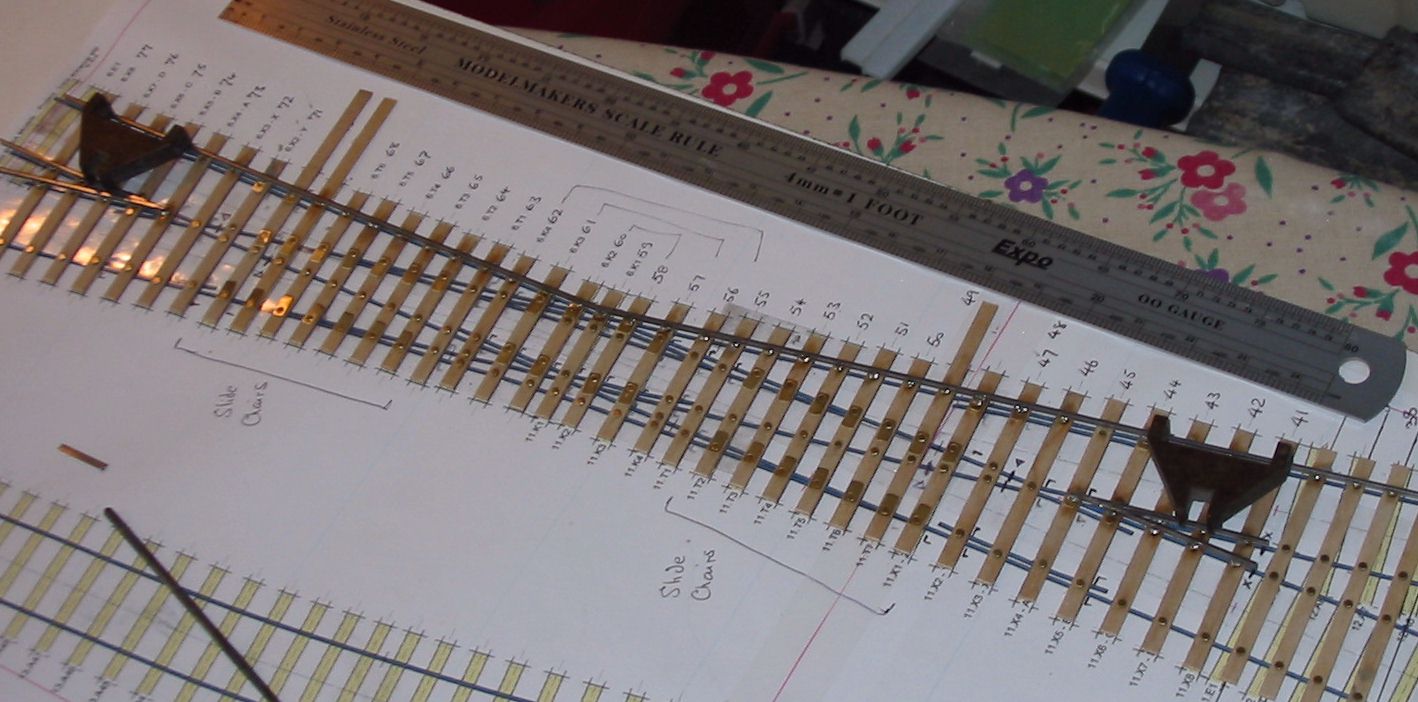
This link http://www.norgrove.me.uk/shed-relay/relay-8l.jpg will get it enlarged a bit.
Regards
This link http://www.norgrove.me.uk/shed-relay/relay-8l.jpg will get it enlarged a bit.
Regards
-
Rod Cameron

- Posts: 850
- Joined: Fri Jul 25, 2008 12:01 pm
Re: Building a Double Slip
Martin Wynne wrote: or else creating your own templates in Templot. That way you can have a curved diamond/slip just as easily as a straight one, and in addition to "regular" diamonds (all angles equal), you can create an "irregular" diamond/slip, for example where a curved track crosses a straight track, as often seen in a double-junction. The Scalefour/Exactoscale templates provide an excellent reference for the chair types and locations.
regards,
Martin.
Sorry for butting in here, but I need to chase that up in Templot, Lewes has a DS and a number of diamonds, most of which have two curved tracks going in opposite directions. So far for the diamonds I've just overlain two plain tracks simply to get the rail alignments.
Rod
-
Martin Wynne
- Posts: 1172
- Joined: Mon May 14, 2012 4:27 pm
Re: Building a Double Slip
Rod Cameron wrote:Sorry for butting in here, but I need to chase that up in Templot, Lewes has a DS and a number of diamonds, most of which have two curved tracks going in opposite directions. So far for the diamonds I've just overlain two plain tracks simply to get the rail alignments.
Hi Rod,
After doing that, have one of them as the control template. Click the background template, and then peg/align tools > make diamond-crossing at intersection menu item.
p.s. this won't work if the crossing angle(s) are shorter than 1:1.5 RAM (33.7 degrees).
For the full chapter and verse, see this video for creating a double-junction with diverging tracks (9 minutes):
help > watch a video > Scruff Video curviform double junction menu item.
More about this at: http://85a.co.uk/forum/view_topic.php?i ... =22#p18015
If the video won't play on your system, it is also available (in poorer MP4 image quality, click it to stop/start playback, it may need several clicks to first start), here:
https://flashbackconnect.com/Movie.aspx ... zpft5UXUA2
If you have the FBR player it can also be downloaded for repeated offline viewing from: http://templot.com/fbr/Scruff_Video_cur ... on___2.fbr
regards,
Martin.
40+ years developing Templot. Enjoy using Templot? Join Templot Club. Be a Templot supporter.
-
Rod Cameron
- Posts: 850
- Joined: Fri Jul 25, 2008 12:01 pm
-
Martin Wynne
- Posts: 1172
- Joined: Mon May 14, 2012 4:27 pm
Re: Building a Double Slip
p.s. Rod,
If watching the MP4 version, in the second part of the video this click on the bottom option bar may be obscured by the playback controls:
Martin.
If watching the MP4 version, in the second part of the video this click on the bottom option bar may be obscured by the playback controls:
Martin.
You do not have the required permissions to view the files attached to this post.
40+ years developing Templot. Enjoy using Templot? Join Templot Club. Be a Templot supporter.
-
jim s-w
- Posts: 2189
- Joined: Wed Jul 30, 2008 5:56 pm
Re: Building a Double Slip
Rod Cameron wrote:
Sorry for butting in here, but I need to chase that up in Templot, Lewes has a DS and a number of diamonds, most of which have two curved tracks going in opposite directions. So far for the diamonds I've just overlain two plain tracks simply to get the rail alignments.
Ooh. Are they switched diamonds?
Jim
-
Enigma
- Posts: 536
- Joined: Tue Aug 13, 2013 2:49 pm
Re: Building a Double Slip
I've started! The 2 vees are in position and, following the Digest instructions, I am now preparing to lay the first stock rail. However, (there's always a 'however' isn't there!) I am finding that my carefully acquired stock of K&L chairs that I am threading onto the rails has become very brittle and are snapping in half as soon as a piece of rail comes anywhere near. I do also have some more recent production ones which seem fine (and the K&L halves can be used around chairs and in awkward situations) but is this a problem anyone else has encountered and, if not, is it a warning to others with similar old stock?
-
Rod Cameron
- Posts: 850
- Joined: Fri Jul 25, 2008 12:01 pm
Re: Building a Double Slip
jim s-w wrote:Rod Cameron wrote:
Sorry for butting in here, but I need to chase that up in Templot, Lewes has a DS and a number of diamonds, most of which have two curved tracks going in opposite directions. So far for the diamonds I've just overlain two plain tracks simply to get the rail alignments.
Ooh. Are they switched diamonds?
Jim
No Jim, just plain, the angles aren't shallow enough to need switching.
Rod
-
dclift
- Posts: 113
- Joined: Sun Jul 26, 2009 1:35 pm
Re: Building a Double Slip
Enigma wrote:...my carefully acquired stock of K&L chairs that I am threading onto the rails has become very brittle and are snapping in half as soon as a piece of rail comes anywhere near.
I have a large number of K&L chairs, purchased from the widow of a deceased member of the Melbourne Finescale Modellers Group some years ago. When I came to use them there was a mortality rate of over 50 % on being threaded onto rail, no matter how much chamfer I put on the rail. The embrittlement of many plastics as they age is a well know phenomenon and has also affected some of my ancient kit-built models. Like Paul, I now have a plentiful supply of half chairs.
David Clift.
-
grovenor-2685
- Forum Team
- Posts: 3922
- Joined: Sun Jun 29, 2008 8:02 pm
Re: Building a Double Slip
There are benefits in ply and rivet  The brittleness won't matter so much when using them as cosmetic half chairs.
bit of a bummer though.
Regards
bit of a bummer though.
Regards
Return to “Track and Turnouts”
Who is online
Users browsing this forum: ClaudeBot and 0 guests