Will L wrote:A relatively well known problem is that it can be quite tricky to avoid a little gauge narrowing through the switch blades. Your description here is typical of what then happens. It is something we all have to watch and often proves to be a particular problem for people building their first points until they get used to looking for it.
Gauge problems through a switch are often caused by failing to put an adequate set in the diverging stock rail.
I have posted this stuff numerous times on RMweb, and also on Templot Club:
http://85a.co.uk/forum/view_topic.php?id=491&forum_id=1so I may as well post it here too:

___________________
Isambard Kingdom Brunel wrote:
"I seem to be having problems with the "SET", does anyone have or can someone take a photo of the "SET" on an actual turnout."
The best pictures I can find so far are in Rod Cameron's post at:
http://www.rmweb.co.uk/forum/viewtopic. ... 72#p190472Here I have marked up an extract from Rod's picture:

The common REA bullhead A, B, etc. switches are "semi-curved" designs. For an ordinary straight turnout, that means there is a straight portion over the length of the tapered planing (machining) on the switch blade, and only beyond that the rails are curved. Here's a diagram to explain it:

Straight turnout:
To make a size B curved stock rail for a straight turnout in 4mm/ft scale, do this:
1. Make two marks on the rail with a fine felt-tip pen, 29.3mm apart.
2. At the first mark make the "set", a sharply-defined shallow bend. Sharply-defined means that it is very clearly in one particular place on the rail, a kink, not a curve. Shallow means it is a very slight angle (1:32 for a B switch). It's very easy to overdo the angle, but you can flatten it back by squeezing the rail in flat pliers.
For a simple way of making a precise bend in rails, see:
http://85a.co.uk/forum/view_topic.php?id=492&forum_id=6
3. Make sure the section of rail between the set and the next mark is dead straight. Don't inadvertently curve it.
4. Beyond the second mark you can gently curve the rail between your fingers.
5. Lay the rail on the template. If it is a Templot template the two marks will be on the template. You can align the rail over the template and check that the set angle matches the template. Time spent at this stage checking and adjusting will be well repaid later. If you have stuck the timbers on the template, it is worth printing off another one to check the rail against more easily.
6. Fix the straight stock rail first, it is just plain rail.
7. Start fixing the curved stock rail at the switch front, gauging from the straight stock rail in the usual way. Don't go beyond the set yet.
8. Transfer your attention to the second mark, location X in the diagram above where the rails begin to diverge. Measure the "stock gauge", that's the distance between the two stock rails at this location, i.e. between X and Y in the diagram. It should be exactly one rail width greater than the track gauge. For 4mm scale that means:
00-SF stock gauge = 16.20 + 0.92 = 17.12mm
EM stock gauge = 18.20 + 0.92 = 19.12mm
P4 stock gauge = 18.83 + 0.92 = 19.75mm
If you don't have a suitable means of making this measurement, you can improvise by combining an oddment of rail with your track gauge tool.
A ready-made 19.75mm stock gauge would be a very handy thing for the Society to supply. The dimension is the same for all sizes of switch.
9. If the stock gauge is correct, you can fix the stock rail at X. If it isn't, you may be able to adjust the set bend slightly in situ. If it is a long way out, you should remove the stock rail and correct the set bend angle. Don't try to correct the stock gauge by curving the rail, the section between the marks must be dead straight as shown.
10. If all is well, you can now fix the rail between the marks, checking with a straight-edge that it is dead straight. Then work forward over the curved section, aligning to the template and gauging from the crossing vee.
For an A switch, the 29.3mm dimension between the marks is shortened to 22.0mm (i.e. the set angle is 1:24). The stock-gauge remains the same dimension as before.
A bit of practice helps of course. Don't expect to get it perfect on your very first turnout. You will soon discover the importance of checking the rail against the template before starting to fix it down.
11. If you get it right you will find adding the switch blades later is dead easy. They will seat properly along the full length of the planing and almost gauge themselves.
You may even want to delay making the switch blades until the stock rails are in place. You can then try clipping them against the stock rails and filing the planing until they seat all along and align correctly at the stock gauge position to give the correct track gauge.
Another point to remember is that switch blades also need a slight set (bend) at the end of the planing, so that the filed front running face lines up with the plain rail beyond. Do this before curving the curved switch blade. Here's a quick sketch of that:
bend_in_switch_rails.png
More diagrams and notes about all this at:
http://www.templot.com/martweb/gs_realtrack.htmCurved turnout:
For a curved turnout the procedure is essentially the same, and it's a good idea to prepare the stock rail first as if it was for a straight turnout. The difference is that the dead straight section should then be curved to match the outer radius for the turnout. In other words the orange-coloured sections on the diagram above are all either straight or all curved to the same radius. The smaller turnout radius (the inner radius) begins only where the rails diverge. The stock gauge and lengths remain unchanged.
To get this right, it's a good idea to print a rails-only copy of the template on tracing paper, and lay it on top of the rails during construction to check the alignments.
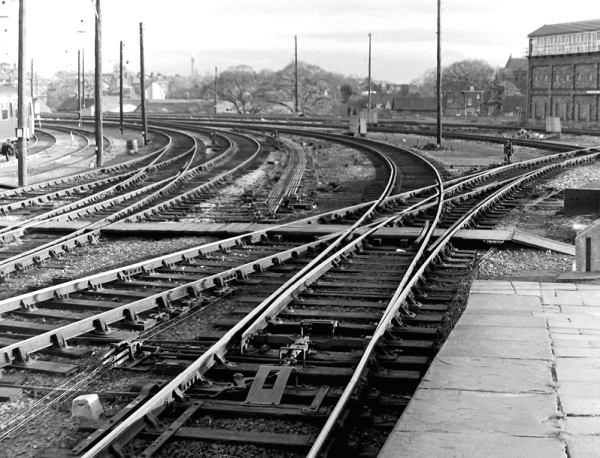
Another picture kindly supplied by Mick Nicholson, showing the "set" bend on an LNER switch:

regards,
Martin.
You do not have the required permissions to view the files attached to this post.