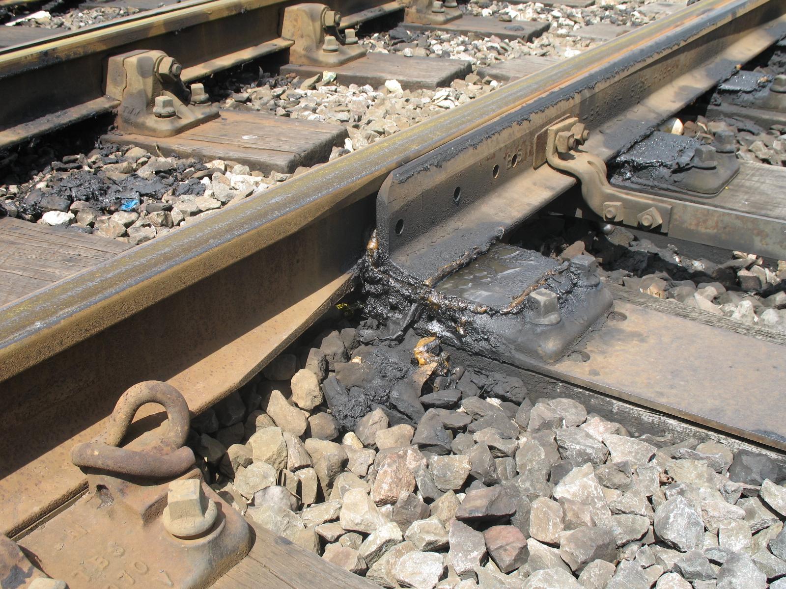
I hadn't really intended to go into the standards in depth, but since the subject has been raised I feel I should point out that there is actually an error with the P4 standards which has been there from day one. In the published standards the quoted figure for the Check Gauge (BB plus EF) is 18.15mm Since the min BB is 17.67mm and the EF is 0.38mm this adds up to 18.05mm not 18.15mm. This means that for a wheelset with 17.67mm BB at a check rail the flange of the opposite wheel wiil not be in contact with the running rail but 0.1mm away from it. This may not seem important, but if the wheelset is running through a crossing with the flange in contact with the stock rail, the back of the opposite wheel flange will strike the knuckle of the crossing as it overlaps it by that 0.1mm difference assuming that the track gauge is the nominal value. The back of a flange is far less forgiving than the front as there is far less rake on it. This is an effect I have witnessed and is exacerbated by the tendency to produce a sharp bend at the knuckle of a Wing rail when it should be a smooth curve. Take a look at my pictures posted above. The latest version of Templot has been modified to include this feature and the difference is notable. If the BB had been set at 17.77mm the figures would add up and perhaps explains why using the max permitted dimension of 17.75mm gives smooth running results.
I have 4 BB gauges and they all have different measurements ranging between 17.67mm and 17.87mm which is slightly worrying. As modellers we depend on our suppliers to apply adequate quality control to achieve consistent results, so it is always worth checking that the gauges we have meet our requirements.
On the full size check rails on curved track are intended to prevent the outside wheel flange from climbing the rail not to take all the side force as it would with the P4 min BB setting.
Apologies for previous errors in this post, which I have now corrected.
Tony.
P4 vs S4 - Pro's and con's
-
Tony Wilkins
- Posts: 818
- Joined: Tue Mar 20, 2012 3:57 pm
Re: P4 vs S4 - Pro's and con's
Inspiration from the past. Dreams for the future.
-
Knuckles

- Posts: 1262
- Joined: Fri Nov 18, 2011 9:15 pm
Re: P4 vs S4 - Pro's and con's
Bit late to say but thank you for all for the replies. I find it all very interesting and there is much to consider for the future. At the start I brought an Exactoscale BtoB of 17.75mm so will keep using it.
I had a few times thought of venturing into S4 but as I'm still fairly new to P4 and would need more generous curves it probably would be a bad move. I worked out that the real world difference would be roughly half inch or less so hardly worth it! Seems only worth it if you have oodles of space to go full blown S4.
I had a few times thought of venturing into S4 but as I'm still fairly new to P4 and would need more generous curves it probably would be a bad move. I worked out that the real world difference would be roughly half inch or less so hardly worth it! Seems only worth it if you have oodles of space to go full blown S4.
“He who dares not offend cannot be honest.” Thomas Paine
https://www.sparkshotcustomcreations.com/
Mostly 3D Printed Loco kits etc.
SCC Price list (7/4/22)
https://www.sparkshotcustomcreations.co ... e77d42.pdf
https://www.sparkshotcustomcreations.com/
Mostly 3D Printed Loco kits etc.
SCC Price list (7/4/22)
https://www.sparkshotcustomcreations.co ... e77d42.pdf
-
Julian Roberts

- Posts: 1394
- Joined: Sat Jan 09, 2010 11:33 pm
Re: P4 vs S4 - Pro's and con's
Tony Wilkins wrote: .....This means that for a wheelset with 17.67mm BB at a check rail the flange of the opposite wheel wiil not be in contact with the running rail but 0.1mm away from it. This may not seem important, but if the wheelset is running through a crossing with the flange in contact with the stock rail, the back of the opposite wheel flange will strike the knuckle of the crossing as it overlaps it by that 0.1mm difference assuming that the track gauge is the nominal value.
The scenario you describe may not be always typical on the straight road of a turnout, surely? - but a wheel will very likely be up against the stockrail on the outside route of a curved turnout, and its opposite wheel will hit the knuckle as you describe. On the diverging route of a typical turnout with a straight main route a wheel will likely be against the closure and knuckle rail, and its opposite will hit the checkrail in the same way, though that has a flare to it.
Is it not the case that whenever there is leeway on the BB the amount of checking going on in either example will be as much as that leeway? The check gauge must not be less than the maximum possible BB plus one flange width, so if the BB can vary up to 0.8mm less than that maximum, then that extra amount of checking must take place, and that degree of rough riding is the inevitable consequence.
The prototype or S4 wheel BB leeway (tolerance) is only 0.02mm.
But, I think, it is unrealistic to imagine it is possible to have wheels with such a small window of tolerance as the prototype because our wheels are mounted in a completely different way. Unless we shrink solid metal wheels onto axles and finish them to gauge in a wheel lathe...? Realistically to expect a less than 0.1 BB variation is optimistic surely, even if we have an accurate BB gauge in the first place? And then too they may shift or wobble. (It amazes me how it was and is possible to work to such small - albeit scaled up - tolerances on the real thing.)
The fabled smooth passage through crossings in P4 is of course a normality because of our near scale crossing flangeway but the checking must always be subject to modelling constraints of BB practicality, surely? Making sure the knuckle bend is not sharp, as you say, is a way of mitigating the problem, and attention to the flares of the checkrail.
Even making these measurements is problematic to a non engineer modeller such as myself. I think I come into the category of person invited in the P4 introductions not to worry about exact measurements and trust the gauges. I had made several locos that run successfully on a reasonably complex club layout before I bought a digital vernier from Lidl. I then discovered the BB gauge I had been using was 17.57 or thereabouts. It had been bought from the EMGS. Now I have a Society BB gauge and that seems to measure 17.67 in the centre of the L shape and 17.75 towards each end. Using the vernier I find it is a matter of touch as to what the second decimal place figure will read. Measuring an actual wheel BB varies with how hard one presses against them, as they can flex outwards, and how square one can place the tool betweeen the wheels. Then there is the possible inaccuracy of the tool itself. I am sceptical of my ability to be nearer than 0.05 even with this technology - a device that used a laser or somehow did not physically touch the wheels would be more trustworthy.
According to this fickle device wheel BB of my stock can vary by an embarrassing amount but still remain on the track at the modest speeds that I find adequate on an exhibiton type terminus to Fiddleyard type layout. I ascribe this to the ability of P4 standards to accommodate the average kitchen table type modeller such as myself for which it was originally aimed, though it seems to me vital to follow the instructions that came with those standards... to have track that is not undergauge in the first place (and some commercial flexitrack is or can be, though Exactoscale Fast Track is not undergauge), and to use the variable gauge widening on curves given by the triangular tool, or its Mark 2 replacement which gave a simple 0.2mm to be used on all curves, which is what the Exactoscale Fast Track does too in its gauge widened for curves version.
Simply the rigour of such a narrow tolerance or leeway on BB in S4 would make it impractical for me, though Andrew Jukes has been describing his use of S4 standards with a bigger BB tolerance, 17.82 - 17.87mm, on another concurrent thread. The more prototypical gauge widening needed does not have to be a problem though - a longer triangular could do the job automatically and roller gauges from C&L can already, but for accurate use require one to know the radius of the curve.
Last edited by Julian Roberts on Tue Apr 25, 2017 7:46 am, edited 2 times in total.
-
Martin Wynne

- Posts: 1172
- Joined: Mon May 14, 2012 4:27 pm
Re: P4 vs S4 - Pro's and con's
Hi Julian,
Throw away your back-to-back gauges.
For best results make yourself a simple wheel setting fixture using your track gauges. See about half-way down on this page:
http://4-sf.uk
The advantage of this method is that your wheels will be matched to your track gauges, even if they are wrong.
regards,
Martin.
40+ years developing Templot. Enjoy using Templot? Join Templot Club. Be a Templot supporter.
-
Julian Roberts
- Posts: 1394
- Joined: Sat Jan 09, 2010 11:33 pm
Re: P4 vs S4 - Pro's and con's
Martin Wynne wrote:Hi Julian,
Throw away your back-to-back gauges....
Thanks Martin! ....Hmm....the layouts I am making stuff for are club or other people's by the way. I see the point of what you are saying though.
Unrelatedly, there is a question about half way down here (below) about what kind of switch is shown in the photo of a turnout at Redhill that maybe you would be interested to answer? - no one else is!
viewtopic.php?f=5&t=5386
-
Martin Wynne
- Posts: 1172
- Joined: Mon May 14, 2012 4:27 pm
Re: P4 vs S4 - Pro's and con's
Julian Roberts wrote:Unrelatedly, there is a question about half way down here (below) about what kind of switch is shown in the photo of a turnout at Redhill that maybe you would be interested to answer? - no one else is!
viewtopic.php?f=5&t=5386
Hi Julian,
Do you mean this one:
What do you want to know about it?
It's obviously flat-bottom. As it was previously part of a scissors crossover, my guess is that it is BS-113A inclined. If it had been renewed as BS-113A vertical, it's very likely the layout would have been simplified at the same time. On the other hand, maybe not as that would make it nearly 50 years old if that is a recent photo?
It obviously isn't a modern overiding NR60 switch, with those BS-113A section switch blades and the cut-away rail foot on the stock rail.
The switch planing is in the chamfered style. Most flat-bottom switches use the chamfered style of planing in which the stock rail is machined:

The above pic is from the excellent collection of Michael Davies in the Templot Club Image Gallery, the large hi-res version is at:
http://85a.co.uk/forum/gallery/1679/ori ... 000001.jpg
Lots more track pics at:
http://85a.co.uk/forum/gallery_view.php ... allery_top
Chamfered planing looks like this (this diagram is for bullhead rail):
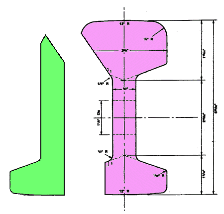
Chamfered planing is very difficult to do in model form. Almost all model rail section has a significantly over-scale web thickness, which limits the scope for tucking the switch rail under the head of the stock rail. And it is very difficult to make the undercut planed angle on the stock rail head using only hand tools. The angle on the switch rail top, and its height, also need to be precisely matched to the stock rail.
I have never seen a model version of chamfered planing in the smaller scales, although there is always a first time of course. Anyone?

If you are wanting to do that switch in Templot, I suggest starting with an FB size CC switch, and seeing how it fits.
regards,
Martin.
You do not have the required permissions to view the files attached to this post.
40+ years developing Templot. Enjoy using Templot? Join Templot Club. Be a Templot supporter.
-
Julian Roberts
- Posts: 1394
- Joined: Sat Jan 09, 2010 11:33 pm
Re: P4 vs S4 - Pro's and con's
Thanks Martin for the detailed reply. My question with the image on the other page was simply whether it was the joggled type of design but I was forgetting, only BH rail can be joggled(?)
Leaving aside the issues involved in actually moving wheels on their axles to the right setting, which I think is easier with a solid block to push them against, if I made this fixture (described in the link) properly as a BB checking device, using P4 check and flangeway gauges (using P4 wheels), the check span should be 17.47 as per the P4 Standards. You say
With the official P4 BB minimum of 17.67 "easily clear" would mean 0.2mm clearance, and with the preferred 17.75 minimum the clearance is 0.28. As I said a few posts back, Andrew Jukes on the "Track and Wheel Standards" has been describing his use of S4 standards with a BB of 17.82. The check span there is 17.67, so he has 0.15 clearance.
What I infer from this is that no great harm will result in going a bit narrow to the official BB. [Not that I would aim for it, but if it happened by mistake and the wheel was stiff to move outwards again or in the case of a driving wheel the quartering might be disturbed (and the grip on the axle is lessened each time one moves the wheel in many cases)]. Your "easily clear" could be as small as Andrew's 0.15, and that would give a 17.62 minimum.
I've found that a BB even in the 17.5's (thus "easily clear" becomes 0.1 or even less) works fine at my low speeds. I understand that the further the BB wanders inwards from the ideal maximum 17.75 the less smoothly it will run through crossings because of the checking, but I wonder what other problems theoretically arise - as so far I haven't had the need and certainly not the inclination to "correct" these errant wheels which occur randomly on some of my locos.
Martin Wynne wrote:Hi Julian,
Throw away your back-to-back gauges.
For best results make yourself a simple wheel setting fixture using your track gauges. See about half-way down on this page:
http://4-sf.uk
The advantage of this method is that your wheels will be matched to your track gauges, even if they are wrong.
regards,
Martin.
Leaving aside the issues involved in actually moving wheels on their axles to the right setting, which I think is easier with a solid block to push them against, if I made this fixture (described in the link) properly as a BB checking device, using P4 check and flangeway gauges (using P4 wheels), the check span should be 17.47 as per the P4 Standards. You say
4. the back of that wheel should easily clear rail 3.
With the official P4 BB minimum of 17.67 "easily clear" would mean 0.2mm clearance, and with the preferred 17.75 minimum the clearance is 0.28. As I said a few posts back, Andrew Jukes on the "Track and Wheel Standards" has been describing his use of S4 standards with a BB of 17.82. The check span there is 17.67, so he has 0.15 clearance.
What I infer from this is that no great harm will result in going a bit narrow to the official BB. [Not that I would aim for it, but if it happened by mistake and the wheel was stiff to move outwards again or in the case of a driving wheel the quartering might be disturbed (and the grip on the axle is lessened each time one moves the wheel in many cases)]. Your "easily clear" could be as small as Andrew's 0.15, and that would give a 17.62 minimum.
I've found that a BB even in the 17.5's (thus "easily clear" becomes 0.1 or even less) works fine at my low speeds. I understand that the further the BB wanders inwards from the ideal maximum 17.75 the less smoothly it will run through crossings because of the checking, but I wonder what other problems theoretically arise - as so far I haven't had the need and certainly not the inclination to "correct" these errant wheels which occur randomly on some of my locos.
-
Martin Wynne
- Posts: 1172
- Joined: Mon May 14, 2012 4:27 pm
Re: P4 vs S4 - Pro's and con's
Julian Roberts wrote:using P4 check and flangeway gauges (using P4 wheels), the check span should be 17.47 as per the P4 Standards. You say4. the back of that wheel should easily clear rail 3.
Hi Julian,
"Easily clear" means a minimum of 0.1mm. This has been found to work acceptably in 00 and EM, so there is no reason for P4 to be different -- indeed the smaller P4 flange depth needs less clearance. 0.1mm is the thickness of ordinary 80gsm office paper. However, that's the minimum -- in practice a bit more is desirable. The clearance is needed to allow for the situation where an axle is skewed from square (radial) across curved track.
The "official" P4 standards are at: http://www.clag.org.uk/p4standards.html
The maximum check span is given as 17.47mm (confusingly called "Between Checks" when it should self-evidently have been called "Across Checks", but it has been that way for 50 years).
This means that the minimum back-to-back is 17.47+0.1 = 17.57mm, or say 17.6mm to be practical with plastic components.
There is no maximum back-to-back dimension. The back-to-flange dimension must not exceed the minimum check gauge of 18.15mm.
If the effective flange thickness is 0.40mm, the maximum back-to-back would be 18.15-0.40 = 17.75mm. If so set, "easily clear" would be 0.28mm.
It is extremely difficult to measure the effective flange thickness, and it varies according to the rail section in use. That's why I suggest using the wheel setting fixture instead of back-to-back gauges. The fixture sets the critical back-to-flange dimension directly, to the optimum setting for the rail section and track gauges in use, without needing to know the effective flange thickness or the resulting back-to-back.
regards,
Martin.
40+ years developing Templot. Enjoy using Templot? Join Templot Club. Be a Templot supporter.
-
Julian Roberts
- Posts: 1394
- Joined: Sat Jan 09, 2010 11:33 pm
Re: P4 vs S4 - Pro's and con's
Martin Wynne wrote:
There is no maximum back-to-back dimension. The back-to-flange dimension must not exceed the minimum check gauge of 18.15mm.
If the effective flange thickness is 0.40mm, the maximum back-to-back would be 18.15-0.40 = 17.75mm.
In the case of S4 or the prototype the back to flange does exceed the check gauge by 0.02mm, given the widest permitted BB.
-
Martin Wynne
- Posts: 1172
- Joined: Mon May 14, 2012 4:27 pm
Re: P4 vs S4 - Pro's and con's
Julian Roberts wrote:the back to flange does exceed the check gauge by 0.02mm, given the widest permitted BB.
Hi Julian,
That's more likely to be an effect of rounding than design intent. Which neatly illustrates the pitfalls of double-dimensioning -- in this case specifying a maximum back-to-back when it is not needed to be specified.
For the best running, the back of one wheel should just kiss the check rail when the flange of the other wheel is running against the rail head.
However, model rail sections vary widely in top-corner radius, and model wheels vary in flange thickness and root profile. Which means the only way to get optimum running in a given case is to use a wheel setting fixture as I described. Throw your back-to-back gauges out of the window, except for one set to say 17.6mm as a GO gauge for testing it is above the desired minimum.
If you want to press your wheels onto the axle to a fixed stop size for all, you would need to set it to allow for your thickest flanges, and squarest rail, and accept that in many cases the result might be less than optimum.
regards,
Martin.
40+ years developing Templot. Enjoy using Templot? Join Templot Club. Be a Templot supporter.
-
Julian Roberts
- Posts: 1394
- Joined: Sat Jan 09, 2010 11:33 pm
Re: P4 vs S4 - Pro's and con's
All very interesting Martin - thanks.
There was something on this Forum not so long ago to the effect that the tool that produces model rail is worn out and therefore no longer giving the correct profile. But the consensus was that it was not badly enough out to produce poor running. But what you say about wheels I find more surprising. I assume, here, you're talking about P4 wheels? Though again I recall it being said here that the wheel profile is also all over the place, but I don't think any particular trader was mentioned.
Martin Wynne wrote:However, model rail sections vary widely in top-corner radius, and model wheels vary in flange thickness and root profile.
There was something on this Forum not so long ago to the effect that the tool that produces model rail is worn out and therefore no longer giving the correct profile. But the consensus was that it was not badly enough out to produce poor running. But what you say about wheels I find more surprising. I assume, here, you're talking about P4 wheels? Though again I recall it being said here that the wheel profile is also all over the place, but I don't think any particular trader was mentioned.
-
Julian Roberts
- Posts: 1394
- Joined: Sat Jan 09, 2010 11:33 pm
Track and Wheel Standards
Martin Wynne wrote:Julian Roberts wrote:the back to flange does exceed the check gauge by 0.02mm, given the widest permitted BB.
Hi Julian,
That's more likely to be an effect of rounding than design intent.
I was surprised, using the decimal figures in the Standards, that in S4 the BB min + EF equals the Check Gauge and BB max + EF exceeds it by 0.02mm - in 4 mm scale.
But using the full size imperial figures the BB min + EF is 1/32" less than the CG, and at BB max + EF it's 1/32" more - so in the middle of the tolerance they are equal, which makes sense:
For the best running, the back of one wheel should just kiss the check rail when the flange of the other wheel is running against the rail head.
Working out all the full size imperial conversions to decimal and 4mm scale on my phone calculator gives some different numbers to those in the Standards, in brackets below, because as you say the effect of rounding, and reducing to two decimal places. (Conversion factors 25.4 and 76.2)
EF = 0.375 (0.38)
BB min = 17.8645833333 (17.87)
BB max = 17.8854166667 (17.89)
The Check Gauge is 18.25. So -
BB min + EF = 18.2395833333 - say 18.24 (18.25)
BB max + EF = 18.2604166667 - say 18.26 (18.27)
which makes sense too.
As I have shown myself to be a complete idiot many times on this Forum when it comes to maths please don't take my word for any of these figures. Please check them someone! I have changed the subject heading as this discussion is equally relevant to that thread.
Last edited by Julian Roberts on Fri May 05, 2017 5:31 pm, edited 1 time in total.
-
Julian Roberts
- Posts: 1394
- Joined: Sat Jan 09, 2010 11:33 pm
BB setting for P4
Hi Martin
I was surprised at your advice to throw away my BB gauge and still more at your advice on the minimum BB being as low as 17.57. All talk I have seen has been on how the minimum of 17.67 was too narrow and that it should be 17.75.
I've had a brief search on BB which yields 269 quotes. Many of them refer to a maker of wagon etc apparatus. Of those referring to Back to Back the huge majority concern Martin Goodall's use of EM wheels on P4 track, correspondents going over and over the same ground. It is relevant to the issue here to summarize his argument, I hope correctly, that EM wheels with a 17.70 BB fit in the same space as taken by P4 wheels at the S4 17.87 BB. He finds they run more reliably - unsurprisingly given that his check gauge is the P4 18.15 and not the S4 18.25.
To find a discussion on the use of 17.75 as the best P4 BB gauge I have to go right back to 2012 viewtopic.php?f=8&t=1764&p=15376&hilit=BB#p15376 "What back to back setting do you use". Here exEditor James has a detailed contribution on the effect of wheel wobble on the BB.
Philip Hall has periodically stated throughout his philosophy as below, that follows his quoting what seems to be the general spirit of the times. This typical quote comes from viewtopic.php?f=37&t=705
Having seen that the prototype maximum BB + EF is only 1/32" more than the check gauge, which equates to 0.01mm, it seems to me pretty vital to follow the same maximum over the CG. And seeing the prototype minimum is only 1/32" less than the CG, I can see how vital it is that the rail and wheel match in contour, as is I assume the case on the real thing. Given our wheel wobble and lack of perfection in the wheel/rail contour it seems obvious we must make a decent allowance for both those factors. At the same time Andrew Jukes has been talking on the Track and Wheel Standards Thread about how the lateral track forces scale down to being much less important than on the real thing, citing his derailment free running of 100 mph trains round 1500mm radius curves as perfectly normal in P4. He happily accepts (if I follow correctly) an overgauge check rail that will significantly jar these trains as they pass through gauge widened pointwork - what would probably derail a real train and destroy the check rail is but a flea bite to the model.
A few months ago I made a 600mm test curve with the Society triangular gauge to test out the gauge widening in practice, and having found it gave perfectly acceptable running for shortwheelbase wagons and loco even at a crazy 25 scale mph, put in the essential parts of a dummy curved turnout, so that the 600mm curve became the outside road of this turnout, to test out what happens if I ignore the presumption against gauge widening in turnouts. Running was completely unaffected by this (worst case scenario) gauge widened curved turnout - yes there is a bit of jarring where the wing rail acts as a check, worsened by the gauge widening, but it is hardly noticeable and certainly not enough to cause derailment. The same applied with my one long wheelbase van. This test is an extreme version of a proper curved turnout - for a start the curve carries on through the crossing. (I also similarly put in a straight diverging road dummy turnout, but here the check rail is at the check rail gauge) (Of course the dummy rails aren't proven accurate as trains don't run on them, but the exercise has a bit of legitimacy I think)
Yes the loco sounds noisy, but it's not going at top speed normally!
So the effect of a narrower than ideal BB is the equivalent - more checking than "ideal". But I am tempted to quote, "Let not the ideal be the enemy of the good" - a bit of slightly harsher checking than ideal is better than a derailment surely?
So I think it may be easy to exaggerate how important the ill effects are of things that would be bad to catastrophic on the real thing...
So having said all that I wonder what your advice is on this Martin: what should my BB gauge measure? You talk about adjusting the BB according to the wheel and rail section in use (and actual track gauges). This is fair enough for a private railway but I make my stock for running on a club layout and other people's layouts, so I can't use a piece of rail that may not be the same section as other ones. And, making loco wheelsets, using Gibson wheels, there has to be a once only fitting of the wheels on the axles, and they are very stiff. Minute adjustment is impossible. If I take them off to try again they progressively become less sure to stay to gauge and in the correct quartering, so the aim is once and once only. For this I need a BB block gauge that is going to give me - first go - adequate, not ideal, running, that will take account of possible flange/rail contour imperfections, and, despite every effort, probably a little wobble, which will be the worse the bigger the wheel. Quite frankly it seems to me the 17.67 is a very sensible gauge as it is half way between 17.76 (allowing an extra 0.01) and your 17.57 minimum.
One thing that comes in here is that the P4 CG is quoted as 18.15 to 18.20. Well that is confusing, as with 18.20, somewhere the 0.68 flangeway is going to be 0.63 unless there is some gauge widening - but the 0.68 flangeway "is preferred" to 0.65 (not .63). And the 17.47 BC doesn't seem to change with this - but am I missing out on something(s) here? Obviously 18.20 can give 17.81 BB with ideal wheel/rail.**
The other end of the spectrum is not mentioned by anyone except James. But Condition 5 (on Page 6 of the 1.2 Digest) says that
That this + 17.47 comes to 17.64 not 17.67 leaves me somewhat baffled as to why say it at all, when 0.2 clearance over the checks was built in the standard if 17.67 was a minimum. (In any case, I don't suppose with your regard to "tablets of stone" this would cause you to revise upwards your 0.1 as being adequate clearance, apart from your already rounding up to a practical 17.60.) I suppose that when in practice it was found less clearance was needed between wheels and running rail, there was no need to investigate whether the 0.17 was also too much.
From what I have read, the problem of a narrow BB seems to be on K crossings, though I have not found that in practice so far on locos where I in my ignorance used a narrow BB gauge.
So I am concluding in the absence of any response to these meanderings as seems to be what sometimes happens ("oh no that crazy gauge widening guy again" ) that Philip's gauge is the one to go for as far as I can see it. A tolerance of 0.06 either way should be do-able. Judging by my efforts so far 0.10 each way might be more realistic though, which the 17.67 already gives (well, + 0.9, - 0.10). With good practice, the gauge should give an actual minimum, and the leeway will be in the + direction only.
Next step - extend this test plank and add the essentials of a K crossing on the straight section.
**Just thought - that 0.05 leeway on Check Gauge is also on the EF measurement. Implying the CG is flexible according to the EF? The S4/prototype table shows no such leeway on the 18.25 CG.
Martin Wynne wrote:
It is extremely difficult to measure the effective flange thickness, and it varies according to the rail section in use. That's why I suggest using the wheel setting fixture instead of back-to-back gauges. The fixture sets the critical back-to-flange dimension directly, to the optimum setting for the rail section and track gauges in use, without needing to know the effective flange thickness or the resulting back-to-back.
regards,
Martin.
For the best running, the back of one wheel should just kiss the check rail when the flange of the other wheel is running against the rail head.
However, model rail sections vary widely in top-corner radius, and model wheels vary in flange thickness and root profile. Which means the only way to get optimum running in a given case is to use a wheel setting fixture as I described. Throw your back-to-back gauges out of the window, except for one set to say 17.6mm as a GO gauge for testing it is above the desired minimum.
If you want to press your wheels onto the axle to a fixed stop size for all, you would need to set it to allow for your thickest flanges, and squarest rail, and accept that in many cases the result might be less than optimum.
This means that the minimum back-to-back is 17.47+0.1 = 17.57mm, or say 17.6mm to be practical with plastic components.
I was surprised at your advice to throw away my BB gauge and still more at your advice on the minimum BB being as low as 17.57. All talk I have seen has been on how the minimum of 17.67 was too narrow and that it should be 17.75.
I've had a brief search on BB which yields 269 quotes. Many of them refer to a maker of wagon etc apparatus. Of those referring to Back to Back the huge majority concern Martin Goodall's use of EM wheels on P4 track, correspondents going over and over the same ground. It is relevant to the issue here to summarize his argument, I hope correctly, that EM wheels with a 17.70 BB fit in the same space as taken by P4 wheels at the S4 17.87 BB. He finds they run more reliably - unsurprisingly given that his check gauge is the P4 18.15 and not the S4 18.25.
To find a discussion on the use of 17.75 as the best P4 BB gauge I have to go right back to 2012 viewtopic.php?f=8&t=1764&p=15376&hilit=BB#p15376 "What back to back setting do you use". Here exEditor James has a detailed contribution on the effect of wheel wobble on the BB.
Philip Hall has periodically stated throughout his philosophy as below, that follows his quoting what seems to be the general spirit of the times. This typical quote comes from viewtopic.php?f=37&t=705
Philip Hall wrote:Craig Whilding wrote:
I think it is widely recognised now though that 17.75mm is the one to aim for and not use the earlier 17.67mm b2b gauges.
I've always thought that in setting the B-B to the maximum value, it's important that wheels don't wobble, but we all know that with the best will in the world, they do sometimes. So I feel a bit of play between the wheels and the track helps no end. When I started in P4, I experimented a little, and worked out that if I had wheels set to the maximum B-B, a slight wobble could put the outer edge of the flange in contact with a crossing nose, so I had a gauge machined up at 17.7mm and have used this dimension ever since.
Philip
Having seen that the prototype maximum BB + EF is only 1/32" more than the check gauge, which equates to 0.01mm, it seems to me pretty vital to follow the same maximum over the CG. And seeing the prototype minimum is only 1/32" less than the CG, I can see how vital it is that the rail and wheel match in contour, as is I assume the case on the real thing. Given our wheel wobble and lack of perfection in the wheel/rail contour it seems obvious we must make a decent allowance for both those factors. At the same time Andrew Jukes has been talking on the Track and Wheel Standards Thread about how the lateral track forces scale down to being much less important than on the real thing, citing his derailment free running of 100 mph trains round 1500mm radius curves as perfectly normal in P4. He happily accepts (if I follow correctly) an overgauge check rail that will significantly jar these trains as they pass through gauge widened pointwork - what would probably derail a real train and destroy the check rail is but a flea bite to the model.
A few months ago I made a 600mm test curve with the Society triangular gauge to test out the gauge widening in practice, and having found it gave perfectly acceptable running for shortwheelbase wagons and loco even at a crazy 25 scale mph, put in the essential parts of a dummy curved turnout, so that the 600mm curve became the outside road of this turnout, to test out what happens if I ignore the presumption against gauge widening in turnouts. Running was completely unaffected by this (worst case scenario) gauge widened curved turnout - yes there is a bit of jarring where the wing rail acts as a check, worsened by the gauge widening, but it is hardly noticeable and certainly not enough to cause derailment. The same applied with my one long wheelbase van. This test is an extreme version of a proper curved turnout - for a start the curve carries on through the crossing. (I also similarly put in a straight diverging road dummy turnout, but here the check rail is at the check rail gauge) (Of course the dummy rails aren't proven accurate as trains don't run on them, but the exercise has a bit of legitimacy I think)
Yes the loco sounds noisy, but it's not going at top speed normally!
So the effect of a narrower than ideal BB is the equivalent - more checking than "ideal". But I am tempted to quote, "Let not the ideal be the enemy of the good" - a bit of slightly harsher checking than ideal is better than a derailment surely?
So I think it may be easy to exaggerate how important the ill effects are of things that would be bad to catastrophic on the real thing...
So having said all that I wonder what your advice is on this Martin: what should my BB gauge measure? You talk about adjusting the BB according to the wheel and rail section in use (and actual track gauges). This is fair enough for a private railway but I make my stock for running on a club layout and other people's layouts, so I can't use a piece of rail that may not be the same section as other ones. And, making loco wheelsets, using Gibson wheels, there has to be a once only fitting of the wheels on the axles, and they are very stiff. Minute adjustment is impossible. If I take them off to try again they progressively become less sure to stay to gauge and in the correct quartering, so the aim is once and once only. For this I need a BB block gauge that is going to give me - first go - adequate, not ideal, running, that will take account of possible flange/rail contour imperfections, and, despite every effort, probably a little wobble, which will be the worse the bigger the wheel. Quite frankly it seems to me the 17.67 is a very sensible gauge as it is half way between 17.76 (allowing an extra 0.01) and your 17.57 minimum.
One thing that comes in here is that the P4 CG is quoted as 18.15 to 18.20. Well that is confusing, as with 18.20, somewhere the 0.68 flangeway is going to be 0.63 unless there is some gauge widening - but the 0.68 flangeway "is preferred" to 0.65 (not .63). And the 17.47 BC doesn't seem to change with this - but am I missing out on something(s) here? Obviously 18.20 can give 17.81 BB with ideal wheel/rail.**
The other end of the spectrum is not mentioned by anyone except James. But Condition 5 (on Page 6 of the 1.2 Digest) says that
The clearance in the above condition represents the sideplay between the inner faces of the wheelset and the width over the outer faces of the check and wing rail pair. In the formulation of P4 standards, a nominal clearance value of 0.17mm was adopted, to take into account the less than prototype equivalent track radii used in models, and the accuracy to which the wheelset BB could reasonably be expected to be maintained within the specified minimum.
That this + 17.47 comes to 17.64 not 17.67 leaves me somewhat baffled as to why say it at all, when 0.2 clearance over the checks was built in the standard if 17.67 was a minimum. (In any case, I don't suppose with your regard to "tablets of stone" this would cause you to revise upwards your 0.1 as being adequate clearance, apart from your already rounding up to a practical 17.60.) I suppose that when in practice it was found less clearance was needed between wheels and running rail, there was no need to investigate whether the 0.17 was also too much.
From what I have read, the problem of a narrow BB seems to be on K crossings, though I have not found that in practice so far on locos where I in my ignorance used a narrow BB gauge.
So I am concluding in the absence of any response to these meanderings as seems to be what sometimes happens ("oh no that crazy gauge widening guy again"
Next step - extend this test plank and add the essentials of a K crossing on the straight section.
**Just thought - that 0.05 leeway on Check Gauge is also on the EF measurement. Implying the CG is flexible according to the EF? The S4/prototype table shows no such leeway on the 18.25 CG.
You do not have the required permissions to view the files attached to this post.
Last edited by Julian Roberts on Tue May 09, 2017 7:19 am, edited 2 times in total.
-
Noel

- Posts: 1983
- Joined: Wed Jun 23, 2010 1:04 pm
Re: P4 vs S4 - Pro's and con's
Julian Roberts wrote: I can see how vital it is that the rail and wheel match in contour, as is I assume the case on the real thing
Actually, no. Designed wheel contours [i.e. before any use of the wheel] can vary within certain limits, as can designed rail contours. Also the angle at which the rail is set [1:20 in the UK] may vary. Finally, both wheel and rail wear in service, so the profiles of both constantly change, hence the need to reprofile from time to time. Wagons which travel over the tracks of more than one administration [train ferries, channel tunnel, etc.] have to be able to cope with whatever conditions they meet, and do. In general, P4 vehicles should similarly run on any P4 track [assuming both are properly built], without the need to enquire about wheel or rail profiles...
Julian Roberts wrote:"oh no that crazy gauge widening guy again"
So far as the P4 situation is concerned, I'm afraid you lost me some time ago, but challenging received wisdom is how we make progress. So even if you turn out to be wrong, in whole or in part, asking the questions is always potentially useful.
Regards
Noel
Noel
-
Julian Roberts
- Posts: 1394
- Joined: Sat Jan 09, 2010 11:33 pm
Re: P4 vs S4 - Pro's and con's
Noel wrote:Julian Roberts wrote: I can see how vital it is that the rail and wheel match in contour, as is I assume the case on the real thing
Actually, no. Designed wheel contours [i.e. before any use of the wheel] can vary within certain limits, as can designed rail contours. Also the angle at which the rail is set [1:20 in the UK] may vary. Finally, both wheel and rail wear in service, so the profiles of both constantly change, hence the need to reprofile from time to time. Wagons which travel over the tracks of more than one administration [train ferries, channel tunnel, etc.] have to be able to cope with whatever conditions they meet, and do. In general, P4 vehicles should similarly run on any P4 track [assuming both are properly built], without the need to enquire about wheel or rail profiles....
Noel I've edited my post above to show why I said how vital it is that the rail and wheel match in contour - I was basically quoting Martin Wynne.
Thanks for your prototype information which tends me to question whether these minute differences of section/contour that Martin talks about are significant enough to be worth bothering about if we are happy to just assume a 0.4 EF.
-
Martin Wynne
- Posts: 1172
- Joined: Mon May 14, 2012 4:27 pm
Re: BB setting for P4
Julian Roberts wrote:Hi Martin
I was surprised at your advice to throw away my BB gauge and still more at your advice on the minimum BB being as low as 17.57. All talk I have seen has been on how the minimum of 17.67 was too narrow and that it should be 17.75.
Hi Julian,
Well yes, "minimum" means not less than.
17.75mm complies with that.
If you want to know what BB setting to use to make your wheels run on all P4 layouts (having track compliant with the P4 standards), set your BB to
not less than 17.57mm,
not more than 18.15mm minus the effective flange thickness.
With the best results if you get as close as possible to the latter dimension without ever exceeding it.
In other words 17.75mm works only if you can rely on the effective flange thickness not exceeding 0.40mm.
regards,
Martin.
40+ years developing Templot. Enjoy using Templot? Join Templot Club. Be a Templot supporter.
-
Julian Roberts
- Posts: 1394
- Joined: Sat Jan 09, 2010 11:33 pm
Re: BB setting for P4
Martin Wynne wrote:[
With the best results if you get as close as possible to the latter dimension without ever exceeding it.
regards,
Martin.
Martin as you have taken the trouble to underline this I assume you don't agree that a 0.01 tolerance in excess is acceptable, although the prototype's tolerance (unless I misunderstand) is in excess, by 1/32", which scales to 0.0104166667mm
I see you are not going to be drawn on the mystery intermediate P4 Check Gauge of 18.20.
Anyway thank you for putting a spotlight on these issues which I had not thought about before.
-
Martin Wynne
- Posts: 1172
- Joined: Mon May 14, 2012 4:27 pm
Re: BB setting for P4
Julian Roberts wrote:Martin as you have taken the trouble to underline this I assume you don't agree that a 0.01 tolerance in excess is acceptable, although the prototype's tolerance (unless I misunderstand) is in excess, by 1/32", which scales to 0.0104166667mm
Hi Julian,
Where did you get that prototype information? Here is some prototype stuff from BRT3:

© PWI
Flange thickness = 1.1/8"
Back-to-back = 4'-5.5/8"
Back-to-flange = 1.1/8" + 4'-5.5/8" = 4'-6.3/4" = check gauge.
Prototype wheel profiles do vary, but we are not building the prototype. Our wheels do not support several tons load. Our wheels do not wear the rail top or wear down to a worn profile. On a model, if the back-to-flange dimension exceeds the check gauge you will at the very least hear a click as the flange hits the nose of the crossing, very likely see a bump, and in many cases get a derailment.
I really don't know where you are trying to get with these topics. This is all basic stuff which hasn't changed since the beginning of P4.
regards,
Martin.
40+ years developing Templot. Enjoy using Templot? Join Templot Club. Be a Templot supporter.
-
Philip Hall
- Posts: 1955
- Joined: Mon Aug 10, 2009 7:49 pm
Re: P4 vs S4 - Pro's and con's
Although I am reluctant to be drawn further into all this, as Julian has mentioned me again in a very recent post can I just say how much I agree with Martin's last sentence. There are hundreds, or maybe just a thousand or two of us, who have been successfully tramping trains up and down and around P4 layouts for donkeys' years now without problems. The standards work, the trains don't fall off and by and large they glide through the pointwork.
My back to back dimension of 17.7 mm seemed a good idea at the time and that was thirty odd years ago. I have standard P4 gauges that measure the same. The standard dimensions allow for some tolerance. The many engines that I have built for others run on their layouts reliably, at some speed in many cases (a lot of them rigid RTR conversions, sorry!) and glide through the pointwork and don't end up in the ballast. Wheels are variously Alan Gibson, Ultrascale, Black Beetle and others. I think that probably proves that it all works, provided you stick to the basic standards.
Looking closely at things can often be rewarding, and can throw up some anomalies, as it might have done here, but I belong to the 'if it ain't broke don't fix it' brigade, and like to get on with making the things. With a fairly big new layout, heaven knows I've got enough of them to build!
Philip
-
Julian Roberts
- Posts: 1394
- Joined: Sat Jan 09, 2010 11:33 pm
Re: BB setting for P4
Hi Philip
Please believe me: I believe you! I would have thought my video was enough to convince you I am quite sure it all works beautifully! - even with my considerably less adequate skills than yours!
All I am interested in, in this discussion, is understanding some things I'd not previously even thought about! - that won't make the tiniest difference, so please don't let me distract you from actually getting on with modelling!
Hi Martin:
http://www.clag.org.uk/p4standards.html ... dimensions
Is this not correct?
Midway between the BBmax and BBmin plus EF = Check Gauge.
So the tolerance is 1/32" (scale 0.01mm) either way from the Check Gauge, is that not so? An amazing standard of perfection whether you look at it from the full size or model perspective - but there's absolutely no need for anyone to model to that tolerance (even if they could!) for the reasons you say. The 1/32" over the Check Gauge isn't causing bangs, bumps or derailments surely?
Please believe me: I believe you! I would have thought my video was enough to convince you I am quite sure it all works beautifully! - even with my considerably less adequate skills than yours!
All I am interested in, in this discussion, is understanding some things I'd not previously even thought about! - that won't make the tiniest difference, so please don't let me distract you from actually getting on with modelling!
Hi Martin:
Martin Wynne wrote:Where did you get that prototype information?
http://www.clag.org.uk/p4standards.html ... dimensions
Is this not correct?
Midway between the BBmax and BBmin plus EF = Check Gauge.
So the tolerance is 1/32" (scale 0.01mm) either way from the Check Gauge, is that not so? An amazing standard of perfection whether you look at it from the full size or model perspective - but there's absolutely no need for anyone to model to that tolerance (even if they could!) for the reasons you say. The 1/32" over the Check Gauge isn't causing bangs, bumps or derailments surely?
You do not have the required permissions to view the files attached to this post.
-
Alan Turner
- Posts: 643
- Joined: Sun Jul 20, 2008 4:24 pm
Re: BB setting for P4
Julian Roberts wrote:
Midway between the BBmax and BBmin plus EF = Check Gauge.
which is 4'-5.5/8" plus 1.1/8" = 4'- 6.3/4". Exactly as Martin quoted above.
regards
Alan
-
Julian Roberts
- Posts: 1394
- Joined: Sat Jan 09, 2010 11:33 pm
Re: P4 vs S4 - Pro's and con's
Alan Turner wrote:Julian Roberts wrote:
Midway between the BBmax and BBmin plus EF = Check Gauge.
which is 4'-5.5/8" plus 1.1/8" = 4'- 6.3/4". Exactly as Martin quoted above.
regards
Alan
So do we agree that the BBmin gives a BB + EF 1/32" less than the check gauge, and BB max gives a BB + EF 1/32" more than the check gauge?
Now please can you look at the missing column below (that I cut out in the previous post)
Check Gauge = 18.25
BB min + EF 17.87 + 0.38 = 18.25
BB max + EF 17.89 + 0.38 = 18.27
But if I metricate all the imperial numbers myself (25.4) and scale them (76.2) the numbers come out differently:
Check Gauge = 18.25
BBmin + EF 17.8645833333+0.375 = 18.2395833333 i.e. 18.24
BBmax + EF 17.8854166667+0.375 = 18.2604166667 i.e. 18.26
This makes no difference to our P4 models, but between one set of numbers and another is a very different way of understanding how the crossing works in principle on the prototype, is not this the case?
You do not have the required permissions to view the files attached to this post.
-
grovenor-2685

- Forum Team
- Posts: 3923
- Joined: Sun Jun 29, 2008 8:02 pm
Re: P4 vs S4 - Pro's and con's
This makes no difference to our P4 models, but between one set of numbers and another is a very different way of understanding how the crossing works in principle on the prototype, is not this the case?
To understand the prototype use the prototype figures without scaling down and rounding off. The rounding errors are of similar magnitude to the prototype tolerances. Also as Martin has mentioned wear and tear has a significant effect on the prototype and wear limits have more of an effect than manufacturing tolerances which are very tight.
Regards
-
Julian Roberts
- Posts: 1394
- Joined: Sat Jan 09, 2010 11:33 pm
Re: P4 vs S4 - Pro's and con's
grovenor-2685 wrote:To understand the prototype use the prototype figures without scaling down and rounding off.Julian Roberts wrote:
So do we agree that the BBmin gives a BB + EF 1/32" less than the check gauge, and BB max gives a BB + EF 1/32" more than the check gauge?
The BB min +EF is 54.23/32"; the Check Gauge is 54.24/32"; the BBmax +EF is 54.25/32"
Keith, thanks for your reply. I don't get this, but it doesn't matter, fortunately, being safely in the nice far larger P4 tolerance (where I hope to continue to stay not above 17.75) and where so far I haven't had any problems! - and I now give up this line of enquiry to get on with some modelling!
You do not have the required permissions to view the files attached to this post.
-
Julian Roberts
- Posts: 1394
- Joined: Sat Jan 09, 2010 11:33 pm
Re: P4 vs S4 - Pro's and con's
grovenor-2685 wrote:Also as Martin has mentioned wear and tear has a significant effect on the prototype and wear limits have more of an effect than manufacturing tolerances which are very tight.
Regards
Is the 1/32" each way that Martin's BRT3 quote doesn't mention a manufacturing tolerance or wear tolerance?
Return to “Track and Turnouts”
Who is online
Users browsing this forum: ClaudeBot, magpie-crawler and 1 guest