Can anybody do me a templot printout?
-
jon price
- Posts: 641
- Joined: Mon Jun 07, 2010 2:34 pm
Can anybody do me a templot printout?
I've looked at Templot, and I dont think I can fit the learning curve into my life, so I'm wondering if an expert Templot jockey could design and print out a turnout for me? The turnout is a tandem, but based on a standard RH A4. The left track is straight on. The centre track should be equidistant/centered between the straight and diverging tracks.
Connah's Quay Workshop threads: viewforum.php?f=125
-
Winander

- Posts: 862
- Joined: Thu Mar 20, 2014 12:19 pm
Re: Can anybody do me a templot printout?
Is it the one on the lhs of the track plan photographed in your post on baseboards here viewtopic.php?f=125&t=4318#p39519 ?
If so it may be easier to design it from the plan, or scan of part of it. You will need to specify the scale and scan resolution (of the original I imagine) to enable the scan to be loaded into Templot and scaled. That way you should get something that will exactly fit the track plan.
If so it may be easier to design it from the plan, or scan of part of it. You will need to specify the scale and scan resolution (of the original I imagine) to enable the scan to be loaded into Templot and scaled. That way you should get something that will exactly fit the track plan.
-
jon price
- Posts: 641
- Joined: Mon Jun 07, 2010 2:34 pm
Re: Can anybody do me a templot printout?
The overall shape is as depicted on the plan, but it has to be modified to avoid baseboard edge/turnout intersections. The curve is a known quantity (2 chains) and pretty well exactly matches (and needs to match for my purposes) the standard A4 configuration, which I have as scale 529mm and 14.25 degrees. I'm not confident that the plan is unaffected by parallax since I took the picture from which it is printed with a hand held camera. If all this is irrelevant in terms of the Templot process then I can supply the image as a JPEG
Connah's Quay Workshop threads: viewforum.php?f=125
-
Alan Turner
- Posts: 643
- Joined: Sun Jul 20, 2008 4:24 pm
Re: Can anybody do me a templot printout?
The left hand turnout that is referred to is not a tandem - it's a three-throw as can be seen by only having one drive-bar position. This means it will be tricky to build and operate correctly.
The turnout is nowhere near an "A4". in fact the nearest is a C/D10 and C/D10.5. As shown:
regards
Alan
The turnout is nowhere near an "A4". in fact the nearest is a C/D10 and C/D10.5. As shown:
regards
Alan
You do not have the required permissions to view the files attached to this post.
-
Martin Wynne

- Posts: 1172
- Joined: Mon May 14, 2012 4:27 pm
Re: Can anybody do me a templot printout?
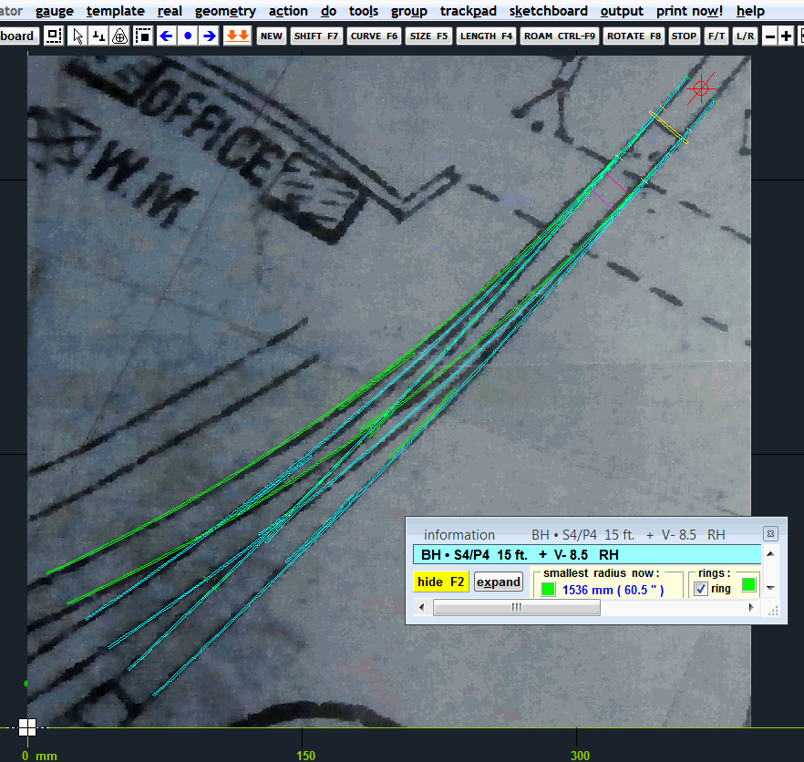
If this is the correct plan (Jon said the outer road is straight -- this one isn't?), then it is not a tandem turnout (with staggered switches), it is a 3-throw turnout (with coincident switches). This is easily seen from the outer crossings being nearly opposite each other and the middle crossing mid-way between the track gauge of the middle road, i.e. near symmetry. 3-throw turnouts are not always symmetrical, but it is difficult for a tandem to be anywhere near symmetrical.
That being so, it is not an A-4 or A anything else, nor a C or D anything. As far as I know there are no 3-throw turnouts using REA switches. This 3-throw will be using straight loose-heel switches.
Having a quick dabble, the inner turnout is approximately a 12ft switch - 1:6, and the outer turnout is approximately 15ft switch - 1:8.5. But it is not that simple -- in a 3-throw each road has one long switch rail and one short one:
regards,
Martin.
40+ years developing Templot. Enjoy using Templot? Join Templot Club. Be a Templot supporter.
-
Guy Rixon

- Posts: 911
- Joined: Sun Mar 27, 2011 6:40 pm
Re: Can anybody do me a templot printout?
Isn't the turnout the one at the extreme lower-left of the plan? I.e. further along the siding fan than the 3-throw. That one looks to be a real tandem and one road looks straight.
-
jon price
- Posts: 641
- Joined: Mon Jun 07, 2010 2:34 pm
Re: Can anybody do me a templot printout?
Thanks for this input Alan and Martin,
I take your suggestion that this is clearly a three way turnout (unfortunately as I will have to try to build two of these). The original plan, though nicely drawn, is quite small scale, and I have blown it up a lot. This I think accounts for the 50% disagreement over radii. Although the track looks accurately drawn the outside width varies on my blown up version from 10 to 17.5mm. In addition the track curves much more sharply between the turnouts.
I have an archaeologist's suspicion of anything I cant measure on the ground, and the working practices of the Buckley Railway sugest that many modern assumptions may not apply. The GCR survey said that the quay was a maze of trackwork where sidings appeared overnight. Certainely all the photos and plans differ quite drastically from each other. Put all this together with the usuual selective compression and I think I am aiming for an impression of the railway because an accurate representation of the actual situation in 1906 would be impossible. For example the plan appears to show the tracks diverging at a slightly interlaced turnout as they enter the site under the bridge, but a photo clearly shows they are not interlaced, just very close (and not very smooth)
Having said that this is a very tight curve. A 1940s photo shows it check railed throughout, though by that time most of the turnouts had been removed. The LNER J62 is standing pretty well exactly where the three way turnout should have been.
My own (scrappy) survey of the remaining few features on the ground (a wall, the bridges, the quay) suggests that the tighter of the two radii you came up with is at the absolute top end of possibility, but the turnout would have to be bracketed by curves with almost half that radius. Whilst that might be real it would start to look a bit like using set track as there would be no transitions. So despite what the plan appears to show I think I am stuck with a minimum radius of maybe 600mm for the turnout and 525mm for the track either side. Such a radius would make the left hand track almost straight. Given that a three way point doesn't conform to the A/B/C system does anyone have suggestions as to how to proceed with the construction of such a creature?
Jon
You do not have the required permissions to view the files attached to this post.
Connah's Quay Workshop threads: viewforum.php?f=125
-
David Knight
- Posts: 822
- Joined: Sun Jul 20, 2008 6:02 pm
Re: Can anybody do me a templot printout?
Jon,
If you have the basic full size outline of where the track is to go it might be just as simple to fall back on a simple flexible spline to lay out the centre line of the track work and proceed to build the turnouts in situ. Templates can be used as a guide for doing the 'iron work' but each bit will need to be custom made for it's position, just like the real thing probably was.
HTH
David
-
jon price
- Posts: 641
- Joined: Mon Jun 07, 2010 2:34 pm
Re: Can anybody do me a templot printout?
thanks David. This sounds like a good plan. The only bits that worry me are,: a) where would I find a guide to which chairs to use at which points (no doubt some are obvious but the double nature of the blade is a slight worry but b) how do I attach the two sets of blades to TOUs
Connah's Quay Workshop threads: viewforum.php?f=125
-
Martin Wynne
- Posts: 1172
- Joined: Mon May 14, 2012 4:27 pm
Re: Can anybody do me a templot printout?
Hi Jon,
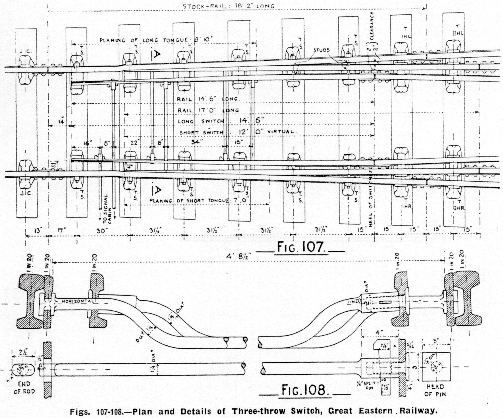
This is what you are trying to build. An exact replica would require custom switches in Templot and a lot of partial templates. It's all doable, but not quickly!
Note that each switch comprises one long point blade (with undercut planing) and one short one (straight-cut joggled).
There are 2 drives (point levers). Each stretcher bar is attached to one long switch blade, and through a hole in the other long blade to the opposite short blade behind it. The drives have to be moved in sequence. Each one must be returned to normal before you can reverse the other. The drawing shows both drives normal, so either can move as drawn.
These switches are 12ft (virtual) and 14ft-6in GER pattern with a common heel position. The 12ft switch has a virtual heel, the actual switch rail is 5ft longer, as can be seen.

The full-size scan can be seen by clicking:
http://85a.co.uk/forum/gallery/2/origin ... 000000.jpg
regards,
Martin.
This is what you are trying to build. An exact replica would require custom switches in Templot and a lot of partial templates. It's all doable, but not quickly!
Note that each switch comprises one long point blade (with undercut planing) and one short one (straight-cut joggled).
There are 2 drives (point levers). Each stretcher bar is attached to one long switch blade, and through a hole in the other long blade to the opposite short blade behind it. The drives have to be moved in sequence. Each one must be returned to normal before you can reverse the other. The drawing shows both drives normal, so either can move as drawn.
These switches are 12ft (virtual) and 14ft-6in GER pattern with a common heel position. The 12ft switch has a virtual heel, the actual switch rail is 5ft longer, as can be seen.
The full-size scan can be seen by clicking:
http://85a.co.uk/forum/gallery/2/origin ... 000000.jpg
regards,
Martin.
40+ years developing Templot. Enjoy using Templot? Join Templot Club. Be a Templot supporter.
-
jon price
- Posts: 641
- Joined: Mon Jun 07, 2010 2:34 pm
Re: Can anybody do me a templot printout?
Thanks Martin, excellent stuff.
Most of this looks like just being careful and methodical work. I would be using plastic chairs and plastic insulated fishplates. The best bet for stretcher rods would seem to be nickel silver wire with a tight fitting plastic sleeve to join them.
Issues I can forsee:
-drilling the holes in the blades lage enough to permit easy sliding of stretchers without destroying the blades in the process
-soldering stub stretcher rods onto the blades so they can slde through the holes AND be joined by an insulating sleeves at exact gauge
-sliding the two long blades into the chairs whilst simultaneously inserting insulated fishplates on all four blades
Has anyone ever made one of these in our scale and gauge? And can they prove it with a photo?
Jon
Connah's Quay Workshop threads: viewforum.php?f=125
-
Andy W

- Posts: 884
- Joined: Thu May 21, 2009 8:11 am
Re: Can anybody do me a templot printout?
Interesting stuff. If I had been an engine driver on the real thing I would have had nightmares about the strength of those buffers, and their proximity to the end of the dock!
Make Worcestershire great again.
Build a wall along the Herefordshire border and make them pay for it.
Build a wall along the Herefordshire border and make them pay for it.
-
Alan Turner
- Posts: 643
- Joined: Sun Jul 20, 2008 4:24 pm
Re: Can anybody do me a templot printout?
Whilst the real one is a three-throw a tandem can be made that will do the job. It's a lot of work to produce a full proper Templot diagram but for modelling purposes of just building it, you don't need that and a plan just to build it is quite straightforward.
The radiuses are tight so it's dock traffic only.
I have used a 15' V9 and a 12' V6. The drive bars are either side of the road crossing (moving blades are not put into crossings as a general rule as debris falls in and stops them working.
here is the solution:
regards
Alan
The radiuses are tight so it's dock traffic only.
I have used a 15' V9 and a 12' V6. The drive bars are either side of the road crossing (moving blades are not put into crossings as a general rule as debris falls in and stops them working.
here is the solution:
regards
Alan
You do not have the required permissions to view the files attached to this post.
-
jon price
- Posts: 641
- Joined: Mon Jun 07, 2010 2:34 pm
Re: Can anybody do me a templot printout?
Thanks Alan
I can't help feeling a tandem would be easier to build than a three throw, although insanity might take hold and get me to go for it anyway.
I can't help feeling a tandem would be easier to build than a three throw, although insanity might take hold and get me to go for it anyway.
Connah's Quay Workshop threads: viewforum.php?f=125
-
John Bateson

- Posts: 809
- Joined: Wed Jul 02, 2008 6:39 pm
Re: Can anybody do me a templot printout?
Since the histories show considerable insanity and malpractice in the WM&CQRR and the Buckley Railway, I wouldn't worry too much. If somebody tells you the track layout is wrong, just explain that their version was yesterdays and the crew did an unauthorised and undocumented addition/alteration. 
Especially don't worry about weak buffers, too close to water, poor brakes or even no brakes on some trains - go for it!
John
Especially don't worry about weak buffers, too close to water, poor brakes or even no brakes on some trains - go for it!
John
Slaving away still on GCR stuff ...
Return to “Track and Turnouts”
Who is online
Users browsing this forum: ClaudeBot and 0 guests