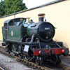
Just a plea for more prototype information, really! I am modelling turnouts based on something like this for my mini-layout. Unfortunately, the photo is a bit small and dark, so it is difficult to work out all the details. I just wonder if anyone has better photos or drawings of anything similar - it doesn't have to be exactly the same, as I am modelling a fictitious railway.
There appear to be two stretcher bars - the nearest is straight and appears to go through a hole in the stock rail towards the point lever. There appears to be a bracket of some kind on the end of the rod, outside the rstock rail connecting to the rod from the point lever.
The far stretcher bar is curved at the ends and is only stretches the width of the point blades.
Old-fashioned Bullhead Turnouts
-
David Bigcheeseplant
- Posts: 338
- Joined: Mon Jun 30, 2008 9:10 pm
Re: Old-fashioned Bullhead Turnouts
I cant help you with the track, but is the photo of Quainton Road with the Manning Wardle Brill No. 1 in the platform?
-
Armchair Modeller
Re: Old-fashioned Bullhead Turnouts
David Bigcheeseplant wrote:I cant help you with the track, but is the photo of Quainton Road with the Manning Wardle Brill No. 1 in the platform?
Yes - but only if the answer won't get me into any trouble
-
Jan
- Posts: 80
- Joined: Mon Aug 11, 2008 3:41 pm
Re: Old-fashioned Bullhead Turnouts
Armchair Modeller wrote:Just a plea for more prototype information, really! I am modelling turnouts based on something like this for my mini-layout. Unfortunately, the photo is a bit small and dark, so it is difficult to work out all the details. I just wonder if anyone has better photos or drawings of anything similar - it doesn't have to be exactly the same, as I am modelling a fictitious railway.
There appear to be two stretcher bars - the nearest is straight and appears to go through a hole in the stock rail towards the point lever. There appears to be a bracket of some kind on the end of the rod, outside the rstock rail connecting to the rod from the point lever.
The far stretcher bar is curved at the ends and is only stretches the width of the point blades.
Ref the lever, bar the orientation of the weight, this one from the Cumbrian Railways Association is similar, and shows the link to good effect.
-
Armchair Modeller
Re: Old-fashioned Bullhead Turnouts
Thanks Jan. That is extremely helpful.
Now, all I need is ideas about the close details of everything that would be below and behind the camera - on my example, or another, similar turnout.
Now, all I need is ideas about the close details of everything that would be below and behind the camera - on my example, or another, similar turnout.
-
Dave K
- Posts: 247
- Joined: Sun Jul 20, 2008 6:11 pm
Re: Old-fashioned Bullhead Turnouts
That point lever looks very much like one that Southwark Bridge Models sell, the 1900 GWR type.
http://www.sbmodels.org/D04a_pointlever(4)gwr.html
http://www.sbmodels.org/D04a_pointlever(4)gwr.html
-
Terry Bendall
- Forum Team
- Posts: 2427
- Joined: Sun Jul 27, 2008 7:46 am
Re: Old-fashioned Bullhead Turnouts
A similar sort of point lever is used on the 2 foot gauge Leighton Buzzard Railway for operating points not used by passenger carrying trains but the weight is the other way round - i.e the lever is dimetrically through the weight. If it would be of any use, I could arrange a site visit for you.
Terry Bendall
Terry Bendall
-
Armchair Modeller
Re: Old-fashioned Bullhead Turnouts
Many thanks for the additional replies - my query is mainly about the stretcher bars though. I guess I didn't make this clear enough. It is unfortunate that the lever is prominent in the photo - it is actually everything else that I really need information on.
Just to recap, the photo shows a stretcher bar that appears to go through the stock rail. My main query is if anyone has drawings or better photos of exact or similar stretcher bars - and the linkage that connects the stretcher bar to the rod from the point lever.
I already have a few point levers from Wizard Models. They will be dummy levers, but thinking about it, getting the levers to flip over would be a cool trick.
-
grovenor-2685

- Forum Team
- Posts: 3923
- Joined: Sun Jun 29, 2008 8:02 pm
Re: Old-fashioned Bullhead Turnouts
Try here, http://www.scalefour.org/resources/trackdetails.html a little way down the page some pics of the round stretchers, doesn't show the lever connection though, which was a different style anyway.
Rgds
Keith
Rgds
Keith
-
Martin Wynne

- Posts: 1172
- Joined: Mon May 14, 2012 4:27 pm
Re: Old-fashioned Bullhead Turnouts
They are old-type stretchers used on loose-heel switches. They fit though a slot in the switch rail, and are locked in position by rotating through 90 degrees, and driving a cotter pin.
Here's a drawing of a GER three-throw with such stretchers:
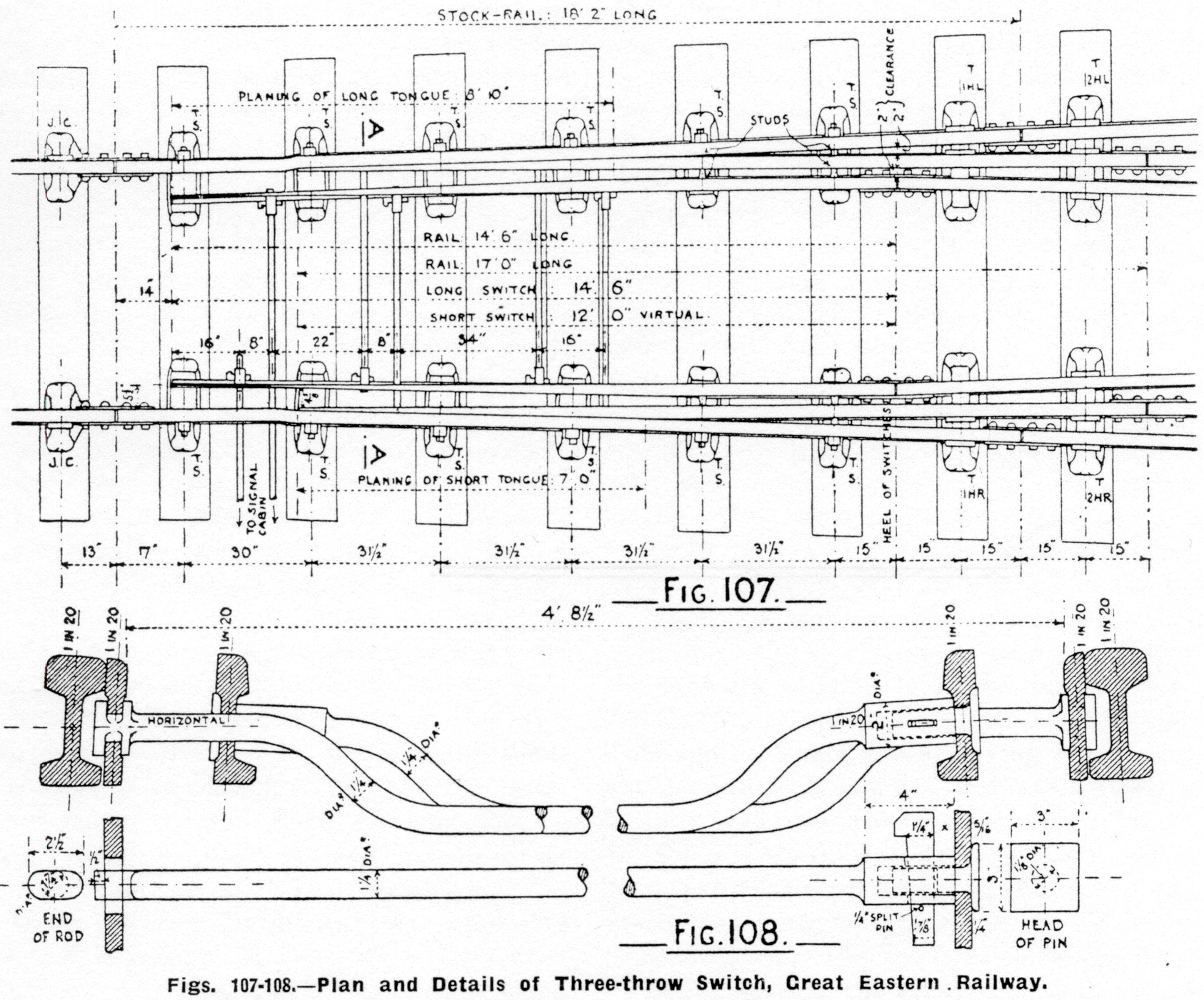
This forum software has cropped it instead of adding scrollbars. Right-click it to download the full image. Here is a smaller version:

Note that each switch comprises one long switch blade (with undercut planing) and one short one (straight-cut joggled). There are 2 drives (point levers). Each stretcher bar is attached to one long switch blade, and through a hole in the other long blade to the opposite short blade behind it. The drives have to be moved in sequence. Each one must be returned to normal before you can reverse the other. The drawing shows both drives normal, so either can move as drawn. These switches are 12ft and 14ft-6in GER pattern with a common heel position.
Here's a drawing of a GER three-throw with such stretchers:
This forum software has cropped it instead of adding scrollbars. Right-click it to download the full image. Here is a smaller version:
Note that each switch comprises one long switch blade (with undercut planing) and one short one (straight-cut joggled). There are 2 drives (point levers). Each stretcher bar is attached to one long switch blade, and through a hole in the other long blade to the opposite short blade behind it. The drives have to be moved in sequence. Each one must be returned to normal before you can reverse the other. The drawing shows both drives normal, so either can move as drawn. These switches are 12ft and 14ft-6in GER pattern with a common heel position.
40+ years developing Templot. Enjoy using Templot? Join Templot Club. Be a Templot supporter.
-
Armchair Modeller
Re: Old-fashioned Bullhead Turnouts
Thanks, Keith - I had missed those on my trawl through the S4 site........
....... and Martin, many thanks for the drawing.
I guess what I am looking for is likely to be very elusive. Perhaps good old common sense will have to fill in the gaps, not that I have much
Fortunately, much of the mechanism was covered over by boarding in the photo, so I can leave some of it to the imagination.
-
Natalie Graham
Re: Old-fashioned Bullhead Turnouts
I presume the stretcher bars in that diagram are only different at either end because of the need for one end to pass though the other switch rail and if fitted to a single turnout would have the thicker section part at both ends. Would that be the case?
-
Martin Wynne
- Posts: 1172
- Joined: Mon May 14, 2012 4:27 pm
Re: Old-fashioned Bullhead Turnouts
Natalie Graham wrote:I presume the stretcher bars in that diagram are only different at either end because of the need for one end to pass though the other switch rail and if fitted to a single turnout would have the thicker section part at both ends. Would that be the case?
Old-type GWR stretcher drawings on the Scalefour web site:
http://scalefour.org/resources/GWRtracknotes/R1775.pdf
Bolts and fittings:
http://scalefour.org/resources/GWRtracknotes/R1730.pdf
Martin.
40+ years developing Templot. Enjoy using Templot? Join Templot Club. Be a Templot supporter.
-
Armchair Modeller
Re: Old-fashioned Bullhead Turnouts
Thanks again Martin  - something else I seem to have missed
These are particularly useful in that they give some dimensions. Not quite like my front stretcher, but at least something to work with. The idea of back stretcher bars conjures up a whole new vision of what track accessories could be used for
These are particularly useful in that they give some dimensions. Not quite like my front stretcher, but at least something to work with. The idea of back stretcher bars conjures up a whole new vision of what track accessories could be used for
-
Jan
- Posts: 80
- Joined: Mon Aug 11, 2008 3:41 pm
Re: Old-fashioned Bullhead Turnouts
Martin Wynne wrote:They are old-type stretchers used on loose-heel switches. They fit though a slot in the switch rail, and are locked in position by rotating through 90 degrees, and driving a cotter pin.
Here's a drawing of a GER three-throw with such stretchers:
http://85a.co.uk/forum/gallery/2/original/2_280950_180000000.jpg
This forum software has cropped it instead of adding scrollbars. Right-click it to download the full image. Here is a smaller version:
http://85a.co.uk/forum/gallery/2/2_280950_180000000.jpg
Note that each switch comprises one long switch blade (with undercut planing) and one short one (straight-cut joggled). There are 2 drives (point levers). Each stretcher bar is attached to one long switch blade, and through a hole in the other long blade to the opposite short blade behind it. The drives have to be moved in sequence. Each one must be returned to normal before you can reverse the other. The drawing shows both drives normal, so either can move as drawn. These switches are 12ft and 14ft-6in GER pattern with a common heel position.
Very grateful for the excellent additional noteage, Martin.
Does anybody else look at drawings of P&C work and marvel at its beauty? Or am I just too weird?
-
jayell
Re: Old-fashioned Bullhead Turnouts
Armchair Modeller wrote:Many thanks for the additional replies - my query is mainly about the stretcher bars though. I guess I didn't make this clear enough. It is unfortunate that the lever is prominent in the photo - it is actually everything else that I really need information on.
some pics from my visit to Maiden Newton
You do not have the required permissions to view the files attached to this post.
-
jayell
Re: Old-fashioned Bullhead Turnouts
P.S,
I forgot this one which puts the stretcher bar pics in context
I forgot this one which puts the stretcher bar pics in context
You do not have the required permissions to view the files attached to this post.
-
Armchair Modeller
Re: Old-fashioned Bullhead Turnouts
Thanks for the photos John - unless I am dreaming that looks suspiciously like a flat-bottomed turnout though.
-
jayell
Re: Old-fashioned Bullhead Turnouts
Armchair Modeller wrote:Thanks for the photos John - unless I am dreaming that looks suspiciously like a flat-bottomed turnout though.
Yes it was a flatbottom turnout 'tacked' onto the bullhead rail through the platform section. The track on each side of the station continues with flatbottom rail.
That turnout led to the goods shed siding with a buffer stop a couple hundred yards away
You do not have the required permissions to view the files attached to this post.
-
Terry Bendall
- Forum Team
- Posts: 2427
- Joined: Sun Jul 27, 2008 7:46 am
Re: Old-fashioned Bullhead Turnouts
johnlewis wrote:P.S,
I forgot this one which puts the stretcher bar pics in context
An interesting application.
My understanding (which my well be incorrect) is that a catch point is designed to derail a vehicle if it runs backwards on a gradient or other situation and usually has a single blade - but does it always?
A trap point will derail a loco or another vehicle if it runs too far forwards, and usually has two blades, as in the picture that John has posted. However this looks like an unusual place to have a trap point next to the end of a platform. Can anyone explain please?
johnlewis wrote:Yes it was a flatbottom turnout 'tacked' onto the bullhead rail through the platform section. The track on each side of the station continues with flatbottom rail.
Colin Criag supplies kits for flay bottom turnouts.
Terry Bendall
-
jayell
Re: Old-fashioned Bullhead Turnouts
Terry Bendall wrote:
An interesting application.
My understanding (which my well be incorrect) is that a catch point is designed to derail a vehicle if it runs backwards on a gradient or other situation and usually has a single blade - but does it always?
A trap point will derail a loco or another vehicle if it runs too far forwards, and usually has two blades, as in the picture that John has posted. However this looks like an unusual place to have a trap point next to the end of a platform. Can anyone explain please?
I don't think that bit of track at Maiden Newton was ever intended to be a catch point but is a remnant of the turnout to the goods shed siding siding that used to be on the 'town' side of the station. If you look at the second of my pictures you will see a block of wood wedging the blade in the open position and there is a bolt fixing the operating rod for the FPL to the sleeper, plus there is no rodding connecting the blades to anything.
Whilst we are talking of catch points I would like to know how they worked, I read of them being 'spring loaded' for example but what sort of spring was used and does anyone have a picture of such a beastie. Toller had at least one trap point that seems to have been linked to one of those mini signals set between the 'main' line and the siding and presumably operated from the 4 lever ground frame set on the platform.
None of the pictures I have found for Toller show any rodding running from the ground frame 'tunnel' to the turnout or trap point or the signal that can be seen in the distance in some pictures. The other end of the siding at the Maiden Newport end had a two lever ground frame according to the signal diagram in the Bridport Branch book but I have no idea if it was enclosed.
John
-
jayell
Re: Old-fashioned Bullhead Turnouts
here is a link to a picture of that turnout before the siding was lifted
http://www.disused-stations.org.uk/m/ma ... ex21.shtml
lot of other pictures on that site too but not many of this end of the station
http://www.disused-stations.org.uk/m/ma ... ex21.shtml
lot of other pictures on that site too but not many of this end of the station
-
Martin Wynne
- Posts: 1172
- Joined: Mon May 14, 2012 4:27 pm
Re: Old-fashioned Bullhead Turnouts
Terry Bendall wrote:A trap point will derail a loco or another vehicle if it runs too far forwards, and usually has two blades, as in the picture that John has posted. However this looks like an unusual place to have a trap point next to the end of a platform. Can anyone explain please?
Hi Terry,
John's picture is not a set of catch points. It's simply the remains of a turnout clipped and locked out of use. There is a point clip visible in one picture, and the facing-point lock is bolted down in the locked position.
The term "trap" points refers to the operational function. The physical object providing the trap function may be a set of catch points (two switch blades), or a single catch point (one switch blade), or a full turnout leading to a siding, spur, or sand drag. Trap points are always connected to the interlocking in a signal box or ground frame.
regards,
Martin.
40+ years developing Templot. Enjoy using Templot? Join Templot Club. Be a Templot supporter.
-
Terry Bendall
- Forum Team
- Posts: 2427
- Joined: Sun Jul 27, 2008 7:46 am
Re: Old-fashioned Bullhead Turnouts
Martin Wynne wrote:John's picture is not a set of catch points. It's simply the remains of a turnout clipped and locked out of use
Thanks for the information Martin.
Terry Bendall
-
Tim V

- Posts: 2870
- Joined: Tue Jul 29, 2008 4:40 pm
Re: Old-fashioned Bullhead Turnouts
Interesting that the current picture shows the remnants of a facing point lock.
My picture shows the same point.
My picture shows the same point.
You do not have the required permissions to view the files attached to this post.
Tim V
(Not all railways in Somerset went to Dorset)
(Not all railways in Somerset went to Dorset)
Return to “Track and Turnouts”
Who is online
Users browsing this forum: ClaudeBot and 2 guests