DaveyTee wrote:I have just "mastered" Templot sufficiently to do a full size print out of my proposed layout (30 or so sheets of A4, carefully stuck together). It involves nine sets of points and quite a lot of plain track. I'm currently building the points off layout, using the templates individually printed off my Templot plan. Other than that, however, if I can't or shouldn't stick the whole plan directly to the baseboard and/or underlay when it comes to track laying the point of using Templot seems considerably diminished. If I stick the plan down I'll know precisely where to lay the points and plain track - if I don't I won't and things are bound to go awry.
Hi Davey,
I prefer not to to leave the template in place under the track. My preferred approach:
1. print 2 sets of the templates. Assemble one set into a full track diagram. Use the other set on the bench for trackbuilding. For reference each page is numbered in the corner inside the trim margins. (There is an option in Templot to increase the font size for those numbers if they are difficult to see.)
2. build the various track items and units.
Now you need a supply of 1" veneer pins (like panel pins, but thinner) from any DIY place.
For plain track:
3. tape the track diagram in place on the bare baseboard with masking tape. Cut away the blank areas between the tracks so that you can do this.
4. tap in a row of veneer pins along the track centre-lines, through the paper templates. Tap them in about half-way.
5. carefully untape and lift away the track diagram over the pins.
6. lay and fix chamfered cork half-roadbeds (C&L/Carrs/other?) with the square edge of each half against the pins. A slight gap down the centre-line between the two halves is of no consequence.
7. when the glue has set, pull out the pins.
8. punch some holes in the track diagram, along the centre lines.
9. tape it back over the cork, using the holes to align it over the joint lines in the cork roadbed.
For areas of pointwork, yards, station throats, junctions, etc., you can lay a full sheet of cork instead of the roadbed strips, taping the track plan to the cork, and omitting 4 to 9 above. Then:
10. carefully align the assembled track items loose on top of track diagram.
11. for each track item, insert veneer pins at a few strategic positions in the corners between the rails and timbers, so that the track is fully located all ways without any play. Keep the pins as vertical as possible, tapping them in about half way.
12. snip the heads off the pins with strong end nippers (
wear eye protection). (Catch the heads, if you don't want to find them later attached to motor magnets and jamming mechanisms.)
13. carefully prise up the track items from between the pins. Without heads on the pins you can do this without disturbing the pins.
14. cut away and remove the relevant part of the track diagram. Make sure other parts of the diagram are sufficiently taped down to remain undisturbed when you do this.
15. apply latex adhesive (Copydex) or contact adhesive to the cork (don't use pva adhesive unless you want noisy track set in concrete).
16. carefully align and drop the track item back over the pins. Firm it down. (Make sure you catch your fingers on the sharp tops of the pins -- bloodstained plywood is just the right colour.

)
17. apply ballast now if you wish (quick) or later after the track is wired up, tested and running for a better result.
18. when the glue has set, pull out the pins.
Above copied from:
http://groups.yahoo.com/neo/groups/temp ... opics/7652Templot2 now includes an option to show the ballast edges and cess lines on the templates. So the above method can be modified to use plain sheets of cork for plain track and cut to the ballast edges directly. There is a gadget available for picture framers which cuts cork at 45 degrees to make a chamfered edge. It should be nearer 30 degrees for ballast shoulders, but the difference is easily lost in the ballasting.
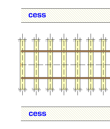
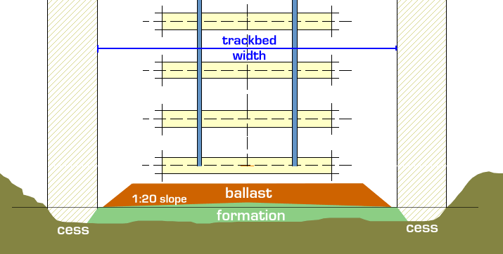
The trackbed edges function can be set to show either the cutting lines for open top baseboards, or the prototypical ballast edge and cess width as above. Click the
geometry > trackbed intent > menu options.
regards,
Martin.