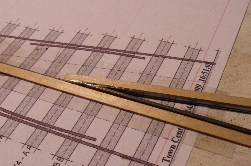
Particularly important with FB to solder upside down in the jig so the heads are properly aligned against the strips although the foot will be overlapping.
regards


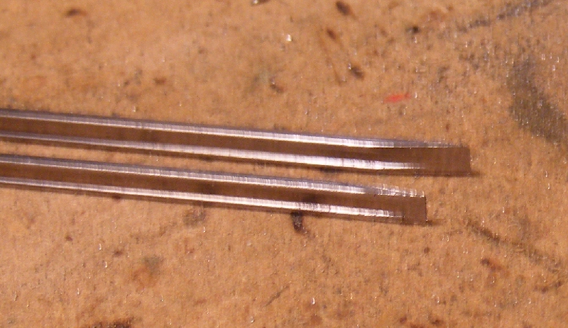
grovenor-2685 wrote:They need to be filed at the crossing angle, 1:8, 1:7 or whatever.
Particularly important with FB to solder upside down in the jig so the heads are properly aligned against the strips although the foot will be overlapping.
regards
Colin Parks wrote:Firstly it is quite difficult to use a template drawn for bullhead rail combined with flat bottom rail - you just lose sight of the position of the rail head, it being obscured by the wider flat bottom rail foot. Secondly, as effective as the Brian Harrap 'folded' crossing vee method is for bullhead rail, it just cannot work with flat bottom rail unless the rail foot on the inside of the fold is removed enough to be flush with the rail head.

All very well I'm sure but I think the reason that Mr blueeighties and so many others are having trouble with their wheelsets binding just slightly on their 'curved' route is because of the natural tendency when constructing a model turnout to position the frog knuckles opposite one another on a plane that is along the 'straight' route. Placing knuckles opposite one another at 90deg to the bisecting angle of the frog circumvents this binding or clipping of the straight knuckle on the curved route and also allows for the increased angle of attack of the flange on the diverging route on LWB vehicles especially. Has always worked for me and I think it looks better. If anyone thinks this is a load of twaddle please carry on in your own way. Regards, Brian
Users browsing this forum: ClaudeBot and 2 guests