Tickled pink about getting a mention by Will in the latest forum notes in Scalefour News.
As a tongue in cheek bit of fun though ... those in the know would know that Le Corbusier's work of 1905, far from being a 'dichotomy', would of course have sat very nicely within the framework of the 'Limestone Hills' of the peak line ... though it is perhaps more suited to the 'Little Switzerland' of Matlock Bath than Monsal Dale itself. In such matters the date is everything! Ha! - but then, he was not actually known as Le Corbusier until a fair few years after this date, so perhaps the dichotomy still stands?
Le Corbusier's Villa Fallet of 1905, situated in La Chaux du Fond in the limestone hills of the Swiss Jura
... and of course Matlock Bath Midland Station
Making a Start - The Peak District Midland / Monsal Dale pre 1903
-
Le Corbusier

- Posts: 1600
- Joined: Wed Feb 11, 2015 3:39 pm
Re: Making a Start - The Peak District Midland pre 1905
You do not have the required permissions to view the files attached to this post.
Tim Lee
-
Le Corbusier
- Posts: 1600
- Joined: Wed Feb 11, 2015 3:39 pm
Re: Making a Start - The Peak District Midland pre 1905
Decided to take the plunge and start on the Johnson 1F 0-6-0T This weekend.
I am going to have a go at using and modifying the chassis which came with the craftsman kit, so we will have to see how we get along.
Craftsman Chassis Etch
I got myself a copy of the original 1F drawing from the NRM, which is a work of art in its own right!From this I was able to make a scale drawing of the correct frame profile, also locating the fire box and ashpan, and the indicated positions of the springs.
Scale drawing of frames
I temporarily soldered together the frame etches, and marked the profile on one side.
I then cut out the profile for both frames together. They still need a little more cleaning up and finessing, but certainly look nearer correct than the originals. I am intending to fill the two holes earmarked in the original for the sand boxes with electrical solder and dress back to the profile. Then I need to scribe the positions for the horn block guides ready for cutting out
I have decided to have my first stab at CSBs with this, so a little reading up (again) is now in order. I shall have a stab at using the spread sheet to come up with a proposed arrangement and would be grateful if people could cast an eye over it to see if I have a workable layout ... and if not give a steer. I have some high-level guides and horn blocks and intend using handrail pillars. When attending Will's workshop at Scaleforum last but one, I came away with the idea that I could work on the basis of equal weight between the wheels and add weight to achieve this? ... then experiment with the gauge of spring for the weight itself, rather than try and calculate everything at the outset?
Looking forward to seeing how all of this is going to pan out.
Tim
You do not have the required permissions to view the files attached to this post.
Tim Lee
-
Will L

- Posts: 2527
- Joined: Sun Jul 20, 2008 3:54 pm
Re: Making a Start - The Peak District Midland pre 1905
Le Corbusier wrote:...When attending Will's workshop at Scaleforum last but one
Actually that was 2011, but doesn't time fly...
, I came away with the idea that I could work on the basis of equal weight between the wheels and add weight to achieve this? ... then experiment with the gauge of spring for the weight itself, rather than try and calculate everything at the outset?
Not quite sure what you meant by so to be sure:-
1. the spread sheet will tell you were the locos centre of gravity should be to achieve the required weight distribution, but at that stage you can't know what the exact weight will be.
2. Once you've built it and balanced it so the centre of gravity is where you want it to be, you can put the true weight back into the spread sheet and use it to tell you what size of wire you need.
Post your plot when you've done it and I'm sure somebody will check it for you.
-
Le Corbusier
- Posts: 1600
- Joined: Wed Feb 11, 2015 3:39 pm
Re: Making a Start - The Peak District Midland pre 1905
Will L wrote:Le Corbusier wrote:...When attending Will's workshop at Scaleforum last but one
Actually that was 2011, but doesn't time fly...
Sorry - used the wrong term - it was your help desk at the 2015 Scaleforum (My first year of membership). Hadn't even heard of P4 in 2011!
1. the spread sheet will tell you were the locos centre of gravity should be to achieve the required weight distribution, but at that stage you can't know what the exact weight will be.
2. Once you've built it and balanced it so the centre of gravity is where you want it to be, you can put the true weight back into the spread sheet and use it to tell you what size of wire you need.
As ever, succinctly put .... that is of course exactly what I meant!
Tim Lee
-
Le Corbusier
- Posts: 1600
- Joined: Wed Feb 11, 2015 3:39 pm
Re: Making a Start - The Peak District Midland pre 1905
This is my attempt at the CSB spreadsheet for the Johson 1F 0-6-0T.
The wheel base is 7'4" - 7'8".
I have assumed uniform weight across the axles (would be interested in a simple way to measure the weight at each axle to ensure this is the case when adding ballast - or do you simply work by trial and error until the loco sits level?).
I have put in a manual value for a to miss one of the etched slots in the frames.
I have one of the High-Level jigs to set out and locate the fulcrum points.
The plan as Will suggested is to weigh the loco on completion and from this determine the csb wire choice.
Hope I have understood this correctly?
If this is all workable, the plan was to locate the fulcrum points using the jig whilst the frames are still soldered together and drill the handrail pillar holes for the wires. Once this is done, I then planned to make the cut outs for the horn blocks and guides prior to splitting the frames.
... that's the plan .... unless there is advice to the contrary
Tim
You do not have the required permissions to view the files attached to this post.
Tim Lee
-
Will L
- Posts: 2527
- Joined: Sun Jul 20, 2008 3:54 pm
Re: Making a Start - The Peak District Midland pre 1905
Tim
The spread sheet is designed to let you know if your choices are reasonable. You will notice that there are two red cells in the OUTPUT section. These are telling you that the current plot isn't good enough.
The one on the left labelled "Chassis Gradient" tells you if the chassis will sit near enough flat. It will be green if the figure is good enough red if it isn't. On your plot its red.
The one on the right labelled "Centre Axle Bias" tells you if the weight carried by the centre axle is close enough to that carried by the outer axles to give effective equal weight distribution. It will be green if it is in the right range and red if it isn't. Yours is red.
You said you adjusted one end to avoid a feature on the chassis. To maintain the balance you will need to adjust the one at the other end as well. Then because you have made the end springs stiffer you will need to adjust the middle two too. The end result would be a plot that goes
a=8, b=14,5, c=14.5 and d=8 . which only means anything in terms of this spread sheet so by convention we usually write this as 8, 14.83, 14.5, 15.5, 15.17, 8 (i.e giving all the dimensions - F1 to W1, W1 to F2, F2to W2, W2 to F3, F3 to W3, W3 to F4 )
However, the auto calculate function on the spread sheet produces what is effectively the shortest practical plot, and reducing the front and rear fulcrums further is probably not desirable, so, if practicable, I'd rather increment the end point rather than reduce them. This gives a plot that goes
a=10, b=15, c=16.5 c=10 ( or 10, 14.33, 15, 16.5, 14.17, 10)
These numbers give you everything you need to recreate the plot on which ever spread sheet you want to use so we don't normally reproduce the spread sheet output. But on this occasion
You will note the two tell tale cells in the OUTPUT section are now green. This section also tells you where the Centre of Gravity for the chassis will need to be, which is in this is case is pretty much over the centre axle as you would expect.
Once you know the loco's final weight (if your picky less the wheels and motor) you enter it into the blue loco weight box near the end of the INPUT VALUES box, then adjust the Spring Diameter to give the defections given in the OUTPUT box as as close to 0.5 as you can get. So if the loco actually does weigh 300 grams it will need 14 thou spring wire.
You do not have the required permissions to view the files attached to this post.
-
Le Corbusier
- Posts: 1600
- Joined: Wed Feb 11, 2015 3:39 pm
Re: Making a Start - The Peak District Midland pre 1905
Thanks Will.
Feel a bit of an idiot missing the red output boxes ... amazing how you miss things late at night The submit button becomes way too attractive.
I have had another bash, as I could really do with moving the outer locations further out now to fully miss obstructions. I might have got away with the 9 value but wanted breathing space. Ditto for 11 ....so for safety I have adjusted to 12. My reading now runs-
12, 12.83, 16.5, 17, 13.67, 12.
C of G is still indicated over centre axle. All values green so I assume all is ok?
I am assuming that in my case - with motor/gearbox/battery/chip/charging point/loco crew and coal - my weight distribution is unlikely to be uniform on all axles. I will therefore have to add weight to achieve uniformity. How do I measure to know where the weight needs to go/when this has been achieved?
Regards
Tim
Feel a bit of an idiot missing the red output boxes ... amazing how you miss things late at night
I have had another bash, as I could really do with moving the outer locations further out now to fully miss obstructions. I might have got away with the 9 value but wanted breathing space. Ditto for 11 ....so for safety I have adjusted to 12. My reading now runs-
12, 12.83, 16.5, 17, 13.67, 12.
C of G is still indicated over centre axle. All values green so I assume all is ok?
I am assuming that in my case - with motor/gearbox/battery/chip/charging point/loco crew and coal - my weight distribution is unlikely to be uniform on all axles. I will therefore have to add weight to achieve uniformity. How do I measure to know where the weight needs to go/when this has been achieved?
Regards
Tim
Tim Lee
-
Alan Turner
- Posts: 643
- Joined: Sun Jul 20, 2008 4:24 pm
Re: Making a Start - The Peak District Midland pre 1905
And this is using the alternative spread sheet:
regards
Alan
regards
Alan
You do not have the required permissions to view the files attached to this post.
-
Russ Elliott

- Posts: 930
- Joined: Thu Jun 02, 2011 6:38 pm
Re: Making a Start - The Peak District Midland pre 1905
Will L wrote:However, the auto calculate function on the spread sheet produces what is effectively the shortest practical plot
booooo....
Tim - I'm Mr Longer Spans Are Better, because longer spans can use thicker wire, and thicker wire tends to be easier to get straight. In a CSB chassis, it is desirable to use wire that is straight.
If the rear of the frame allows it, I'd be more tempted by a=13.5, b=16, c=19.5 d=16.5.
-
Le Corbusier
- Posts: 1600
- Joined: Wed Feb 11, 2015 3:39 pm
Re: Making a Start - The Peak District Midland pre 1905
Russ Elliott wrote:Will L wrote:However, the auto calculate function on the spread sheet produces what is effectively the shortest practical plot
booooo....
Tim - I'm Mr Longer Spans Are Better, because longer spans can use thicker wire, and thicker wire tends to be easier to get straight. In a CSB chassis, it is desirable to use wire that is straight.
If the rear of the frame allows it, I'd be more tempted by a=13.5, b=16, c=19.5 d=16.5.
Thanks Russ,
I will see if I can make that or something close work.
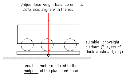
Do you have a method of adding weight (lead) to the loco such that you know where to add in order to achieve a uniform distribution? If the pivot point is over the central wheel, I suppose you could rig up a balance and add weight by trial and error until it sits horizontal? I just felt sure there would be a simple method.
Tim
Tim Lee
-
Russ Elliott
- Posts: 930
- Joined: Thu Jun 02, 2011 6:38 pm
Re: Making a Start - The Peak District Midland pre 1905
Le Corbusier wrote:Do you have a method of adding weight (lead) to the loco such that you know where to add in order to achieve a uniform distribution? If the pivot point is over the central wheel, I suppose you could rig up a balance and add weight by trial and error until it sits horizontal? I just felt sure there would be a simple method.
http://www.clag.org.uk/pics/beams/c-of-g.png
-
Le Corbusier
- Posts: 1600
- Joined: Wed Feb 11, 2015 3:39 pm
Re: Making a Start - The Peak District Midland pre 1905
Russ Elliott wrote:Le Corbusier wrote:Do you have a method of adding weight (lead) to the loco such that you know where to add in order to achieve a uniform distribution? If the pivot point is over the central wheel, I suppose you could rig up a balance and add weight by trial and error until it sits horizontal? I just felt sure there would be a simple method.
http://www.clag.org.uk/pics/beams/c-of-g.png
Brilliant .... simpler than what I was contemplating
Thanks
edit - just noticed that Russ has actually dealt with this question from me on a previous thread .... thanks for the patience, must be losing it
Tim Lee
-
Will L
- Posts: 2527
- Joined: Sun Jul 20, 2008 3:54 pm
Re: Making a Start - The Peak District Midland pre 1905
Russ Elliott wrote:Will L wrote:However, the auto calculate function on the spread sheet produces what is effectively the shortest practical plot
booooo....
Tim - I'm Mr Longer Spans Are Better, because longer spans can use thicker wire, and thicker wire tends to be easier to get straight. In a CSB chassis, it is desirable to use wire that is straight.
If the rear of the frame allows it, I'd be more tempted by a=13.5, b=16, c=19.5 d=16.5.
And there was me thinking I'd get some credit from Russ for suggesting Tim pushed the end fulcrums out a bit.
While I agree that plot works and gives valid answers from the spread sheet, it seems strange to have significantly different end span lengths when the wheel base is only just off symmetrical. And I have reservations about the 16.5 mm length at one end.
Beware dancing angles
As Russ and I are well aware there is no one right answers here and there are many possible plots, however as the end span lengths get more extreme, either very long or very short, the results become increasingly mathematically unstable. A lot of playing with the spread sheet suggests empirically that for a 3 axle chassis the sweet spot is anywhere between 1/4 of the overall wheelbase (in this case 15) and the auto calculate value (in this case 9). The point being that solutions from the sweet spot are robust enough to ensure that minor variations in the actual position of the effective fulcrum point wont adversely affect the performance of the chassis, with solutions outside the sweet spot this robustness of outcome becomes less certain. Both Tim's original 8 and Russ's 16.5 are outside the sweet spot.
-
billbedford
Re: Making a Start - The Peak District Midland pre 1905
At the risk of adding to the confusion, I would put the anchors at a=10, b=c, d=e & f=10. For near symmetrical frames this gives a solution that is easily remembered, i.e. a = f = 1/6 * wheelbase, but also puts the anchors and bearings close to the asymptotes of the natural curve of the spring wires. See this page for further info
-
Will L
- Posts: 2527
- Joined: Sun Jul 20, 2008 3:54 pm
Re: Making a Start - The Peak District Midland pre 1905
billbedford wrote:At the risk of adding to the confusion, I would put the anchors at a=10, b=c, d=e & f=10. For near symmetrical frames this gives a solution that is easily remembered, i.e. a = f = 1/6 * wheelbase, but also puts the anchors and bearings close to the asymptotes of the natural curve of the spring wires. See this page for further info
Which as near as damit is the method used by the auto calculate function of my spreadsheet.
-
Le Corbusier
- Posts: 1600
- Joined: Wed Feb 11, 2015 3:39 pm
Re: Making a Start - The Peak District Midland pre 1905
Could anyone point me in a direction where I might find dimensional information for heights and layouts of typical public goods wharfs (for small stations)? I assume that these would have been standardised to some extent. Style apart, would there have been much difference between the companies.
Any suggestions for a bit of research reading as a beginner's primer would be appreciated.
Tim
Any suggestions for a bit of research reading as a beginner's primer would be appreciated.
Tim
Tim Lee
-
Armchair Modeller
Re: Making a Start - The Peak District Midland pre 1905
MRJ 23 has a list of standard MR dimensions - height above rail level
Goods & mineral loading stages...
general goods/horses/cattle 3ft 6in
High sided wagons with minerals etc by tipping 8ft
Carriage loading docks 4ft
Goods & mineral loading stages...
general goods/horses/cattle 3ft 6in
High sided wagons with minerals etc by tipping 8ft
Carriage loading docks 4ft
-
Le Corbusier
- Posts: 1600
- Joined: Wed Feb 11, 2015 3:39 pm
Re: Making a Start - The Peak District Midland pre 1905
Armchair Modeller wrote:MRJ 23 has a list of standard MR dimensions - height above rail level
Would that be the Model Railway Journal ... or Midland Record Journal ?
Is it worth getting a copy or is there little more information than you quote ?
Thanks
Tim
Tim Lee
-
Noel

- Posts: 1983
- Joined: Wed Jun 23, 2010 1:04 pm
Re: Making a Start - The Peak District Midland pre 1905
The layout of structures within a goods yard would vary according to the shape and size of the yard [the weighbridge, if any, was usually alongside the entrance/exit, for example]. However, the types of structures present would be similar, as all companies would be handling very similar traffic. One of the main exceptions to this were the companies, such as the NER, who handled all coal traffic themselves, using hoppers, which meant that their stations normally had coal drops. Another possible exception is very early lines, which were often built to deal with one specific traffic, and sometimes never updated.
Structures might be added or removed over time, depending on the changes in amount and type of traffic the yard was handling. Sometimes an extra siding or two would be added, or sometimes a siding would be extended. Sometimes the whole yard layout would be altered [some early yards had most of the facilities accessed off a wagon turntable, for example, which had to be altered when traffic increased]. The original structures might have been designed by the contractor who built them, with later ones design by the company, whoever built them. Company's architectural and civil engineering designs could also change over time. In addition, coal merchants, or agricultural wholesalers, for example, might build structures of their own or the railway might build them and lease them out. These might be very different in style to earlier buildings.
Mileage sidings [track alongside ground level vehicle access] were always present; other facilities could include end loading, side loading, a goods shed of some sort, a cattle pen or pens in country areas or market towns, and possibly a crane [several different capacities existed]. Other facilities might exist for specific traffic, but equally some or all of the facilities listed might be missing. Basically it depended on how much of what traffic the company expected to get when the line was built, and whether the traffic exceeded these expectations. The expected traffic would also affect the size of structures in some cases; the Midland, for example, built three different sizes of goods shed on the Settle and Carlisle, but half of the stations had no goods shed at all.
Public railway companies were common carriers, so had to deal with, in theory, any traffic offered, with few exceptions. Similar problems resulted in similar solutions, but changes in designs over time plus variations in origins and dates of structures meant very little standardisation in detail.
David Jenkinson's "Rails in the Fells" is about the S & C, but is the only book I have come across which analyses the facilities available at a group of country stations, and the changes in their traffics over time. His "Modelling Historic Railways" shows how he used the economic geography of the area to establish traffic likely to be offered, and hence the facilities required, for a proposed layout. If you don't want to go that far, Bob Essery's "Railway operation for the modeller" and its sequels may be helpful. Unfortunately, to enthusiasts, goods traffic was always a lot less interesting, a lot more complex, and a lot less accessible, than the more glamourous express passenger traffic, so there is rather less data available.
Regards
Noel
Noel
-
Armchair Modeller
Re: Making a Start - The Peak District Midland pre 1905
Le Corbusier wrote:Armchair Modeller wrote:MRJ 23 has a list of standard MR dimensions - height above rail level
Would that be the Model Railway Journal ... or Midland Record Journal ?
Is it worth getting a copy or is there little more information than you quote ?
Thanks
Tim
Definitely a good idea - MRJ is meant to be Model Railway Journal. It quotes all the key dimensions for the MR track and structures - though these would probably be ideal. Older lines in particular might have been built to tighter standards.
-
Le Corbusier
- Posts: 1600
- Joined: Wed Feb 11, 2015 3:39 pm
Re: Making a Start - The Peak District Midland pre 1905
Firstly, Thanks Noel for the advice on loading bays.
On a completely different subject ... I wondered if people might have suggestions/recommendations for reasonably priced laser cutting work?
What sort of prices should I expect/how does pricing work?
Are there any hobby laser cutter machines out there that are any good to buy without breaking the bank?
Tim
Tim Lee
-
Jol Wilkinson

- Posts: 1115
- Joined: Mon Jul 21, 2008 7:39 pm
Re: Making a Start - The Peak District Midland pre 1905
Tim,
for the parts I wanted for the LNWR footbridge (S4 News 189) were laser cut by Jonathan Buckie of Clockwork ideas. He was very helpful about the artwork design.
I can't find a website address for him, but he is a member of the Society and also the South Hants AG.
Jol
for the parts I wanted for the LNWR footbridge (S4 News 189) were laser cut by Jonathan Buckie of Clockwork ideas. He was very helpful about the artwork design.
I can't find a website address for him, but he is a member of the Society and also the South Hants AG.
Jol
-
NorthHighlander
- Posts: 42
- Joined: Fri May 24, 2013 10:17 pm
Re: Making a Start - The Peak District Midland pre 1905
Yes, I can vouch for Jonathan's work... he has produced several cuts for my Brighton layout.
Tony Hagon
Tony Hagon
-
dal-t
- Posts: 654
- Joined: Mon Jan 11, 2010 8:06 pm
Re: Making a Start - The Peak District Midland pre 1905
Jonathan has a dedicated email address <enquiries@clockworkideas.co.uk> (it's already public in another place so not breaking any confidences here).
David L-T
-
Highpeak
- Posts: 127
- Joined: Sat Oct 13, 2012 8:33 pm
Re: Making a Start - The Peak District Midland pre 1905
During my recent visit to the Peak District I walked the line from Millers Dale to Bakewell and measured up the dock at Monsal Head.
Starting at the Millers Dale end, the height (and these figures are approximations because it is not very easy to determine where exactly the ground level is) is 4'. This height is maintained for 12' and then an upward slope starts to raise the height to about 6'. The length of the slope is about 18'.
The raised part of the dock is about 27 yards long and then drops down to the lower height, the length of that slope is about 16 yards, very gradual. Presumably this was so that loaded carts could be pulled up to the higher level.
The final lower part of the dock is about 15 yards long.
If you look closely at the stone work I think you can see how the height was raised, there seems to be a definite straight line at around the three to four foot height with a more random arrangement of stones above it:
I hope this helps. The height measurements are, as I said, only approximate because of the tangle of undergrowth.
You do not have the required permissions to view the files attached to this post.
Neville
If at first you don't succeed, try reading the instructions.
If at first you don't succeed, try reading the instructions.
Who is online
Users browsing this forum: AhrefsBot, ClaudeBot and 1 guest