The next phase:
-
doggeface
The next phase:
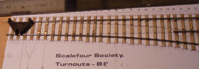
Having now cleared the piste of the remaining 00 evidence and the laying of a fresh working surface it came time to carry on with some point and track building. Today saw the final joint of the B6 cross over set ( less tie bars which still pose a few problems); I must say that the construction of this second pair ran very easily and I hope that my experiences with this job will encourage the others (not in an admiral Bing manner). The thing most easy turns out to be the fabrication of the nose and switch blades. Nickle is very easy to file and a blade does not take more than 20 mins to produce. The one thing which remains large on my horizon is just how one cosmetically treats the solder mounts to look lke chairs! Any advice is very welcome.
-
Paul Willis

- Forum Team
- Posts: 3048
- Joined: Sun Jul 20, 2008 6:00 pm
Re: The next phase:
doggeface wrote:Having now cleared the piste of the remaining 00 evidence and the laying of a fresh working surface it came time to carry on with some point and track building. ... The one thing which remains large on my horizon is just how one cosmetically treats the solder mounts to look lke chairs! Any advice is very welcome.
Hi Peter,
Congratulations on your progress! You're certainly getting on at a far better rate of knots than I seem to manage.
You asked about representing chairs. To answer your question as originally asked, I suppose that if you have a blob of solder on the edge of a rail, you would attack it with a scraper or scalpel to get a representation of the shape.
However the usual solution with ply-and-rivet construction is to apply cosmetic chairs of the appropriate (for you can get ones that are 2-bolt, 3-bolt or 4-bolt, depending on your prototype) style and glue them in place.
There used to be cast whitemetal chair "halves" that were sold (I still have an unopened pack!) but these were quite crude. The standard thing today is to use a functional plastic chair from C&L or Exactoscale, slice it in half with a scalpel, and apply one half to each side of the rail. This means that you can trim it to fit exactly over/around the rivet.
Of course, doing a large section of track is a bit of a thankless task, which explains the popularity of the plastic track styles of construction these days, or even the use of "RTR" plain track in metres lengths!
You can find details of the chair types available and some pictures (hover over the thumbnail) here: http://www.finescale.org.uk/index.php?option=com_virtuemart&Itemid=51#chairs
HTH
Flymo
Beware of Trains - occasional modelling in progress!
www.5522models.co.uk
www.5522models.co.uk
-
doggeface
Re: The next phase:
Well time has been passing and I have tried to mix track building with RTR loco modifying. Keith very kindly proposed a set of prints for a large radius curved crossover. This was interesting as several lessons have resulted, not the least being the comparative radii involved at 1.4 m and the way forward to drawing tighter curved crossings on the drawing board (yes I even leave my slide rule in view nestling up to my 30 year old Texas Inst PE cell driven calculator!). The problem of construction immediately became an issue. I was not keen on unit construction no matter how prototypical it may be as I wanted there to be no errors! The only solution was to build it in situ (luckily it is reachable) and so the sheets were glued down and ties cut using the continuous tie principle for the centre section. Each tie was cut to length, marked with a drawing pen for rail rivet position then removed for drilling (dremel) and rivetting -hand hammer method. The completed tie was then glued into position using prit stick type applicator. Luckily the necessary rail turned up but the pre drilled ties for the "easy" part have become unavailable from the stores so that job stopped. Chairs from the usual suspects are still walking although after 3 weeks must be getting very tired! The rewheeling of a second Bachmann Pannier tank ceased when bought in "as new" loco turned out to be rather cranky and unfit for DCC conversion -- the replacement wheel set should arrive sometime soon.
Comet delivered a chassis for one of the 14XX 0-4-2 s and that has occupied my waiting moments and procurement skills! The motor section of the chassis is now functional and ready for static running in as recommended. I started this intending to build it in the semi compensated form (weight distributed to the trailing wheel set and a fore&aft rocking freedom on the driving pair via a subframe. The freeing of the gearbox produced a steep learning curve including the fact that several small reamers are essential (thank goodness for hong kong). The subframe for the driver bearings in this arrangement are a long way from the P4 frame plate so I shall have to pad it out with whatever comes to hand. During the research for this project it became evident that the RTR chassis is capable of being P4'd so I have ordered up for that project (Gibsons need plenty of time to deliver) but even if that works well I shall go the whole hog with another Comets chassis and fit hornblocks and maybe to the trailing axle also.
My eye is constantly roaming over the kits which can result in locos which did,may have and could have run over the Severn & Wye section so making 2021 s out ofhybrid Hornby and a Bachmann chassis plus a few saddle tanks which existed until the 1930's
The main lesson however has been how to recover the patience of my submarine days and how to compensate for the lack of youthful eyesight! My admiral Bing moment has now passed with the sale of the last OO track but it has not escaped my notice that the two boxes of rolling stock are not easy to lift.
I still seek an efficient adhesive for fixing down plastic chairs first time!
-
doggeface
Re: The next phase:
I have a couple of photos which illustrate the extreme length of a 1.4M curved cross over!
This is the schematic plan in place with just one nose ready to fix in place.
After a long afternoon I managed to reach the stage shown in the second shot:
The next couple of days saw various attempts to correct the out of gauge places - this mostly due to poor eyesight and lighting. The one I can cure but the othe is price of anno domini! I have managed to progress further with this project. Some Exactoscale fishplates arrived today so maybe I can make some decent rail joints.
Best Regards
Peter
You do not have the required permissions to view the files attached to this post.
-
doggeface
Re: The next phase:
I did forget to mention that the other project vying for time -- the GW 14XX - actually ran (chassis only) on a length of track powered by trailing wires from the bench test P.U.
-
Mark Tatlow
- Posts: 899
- Joined: Tue Dec 02, 2008 11:24 pm
Re: The next phase:
You are certainly getting on - well done!!
Indeed, putting me to shame....................best get back to the modelling desk!
Indeed, putting me to shame....................best get back to the modelling desk!
Mark Tatlow
-
doggeface
Re: The next phase:
The progress continues on the long curved crossing! The Exactoscale brass fishplates are rather good and even the pvc ones are not bad. The crossing is mechanically intact but it is proving difficult to sort out pinch points and uneven rail heights (seems to be a regular thing using rivet and solder assembly.
The little 14XX chassis has run nicely over 50 cms of track on its umbilical cabling but I have managed to skew one of the rear dummy spring blocks so that will need to be corrected. Equally the proposal to convert the other by a simple wheel swap looks to be very feasable (I will soon find out once the correct trailing wheel set arrives).
I had ambitions to P4 a hornby large prairie but as no one does a simple kit I stripped one down and immmediately recognised the problem --- 3mm driving axles! Nothing that a 1/8" reamer could not put right! Equally the not so robust plastic motion gear has not been available for years so a Comet Cyl, motion and conn/crank rod set will do the job. Otherwise this model has a lot going for it both in appearance and also the elegant chassis arrangement.
Whilst testing a newly arrived Bachmann (nearly new) GW pannier which was reported to make a clicking noise when running -- I discovered that none of my stock of wheel sets could cure the problem. So! I replaced the entire wheel set and connecting rods together with the gear train --- result = no change!
Some serious measuring followed and sure enough the fault lay in the axle slots (not so simple to measure with the centre bearing being mounted on a rotor. The sole solution was to reamer out the crank pin holes and now it runs peacefully enough but not really good enough to fit P4 wheels and DCC chips to !
The next step when materials arrive, will be to construct a B6 parallel crossing which I have produced on my A3 drawing board. I had been rather concerned about sleeper spacing but now that I have constructed track using exactoscale, S4 soc and Templot proformers and paper templates I discover that they are all wildly different. Difficult to see variations such as 9' or 8'6" sleepers makes me wonder why bother?
I must say that the hobby is a great help in dealing with the avaricious whinging monsters otherwise known as EBay buyers -- I really would have been better served taking all my unwanted stuff to the tip! Oddly enough our mayor (a rail fan) told me on Friday that his son saw a chap do exactly that at the other end of the county! Pierreot was quick to ask his son to recover some of it and every piece was recuperated including some very fine multi wheeled locos. This in a land where 300€ does not buy you very much.
You do not have the required permissions to view the files attached to this post.
-
grovenor-2685

- Forum Team
- Posts: 3923
- Joined: Sun Jun 29, 2008 8:02 pm
Re: The next phase:
You're making good progress there, the crossover coming out well.
It should not be, possibly a technique issue?
There are two common sources for uneven levels, first is uneven rivetting where some rivets are not set flush with the bottom of the timber. Its the rivetted depth of the rivets that controls the evenness of the top surface, especially when using a hard surface to build on. This is where the press tool scores over a hammer but either way the essential is to have a recess the depth of the head to hold the rivet whilst it is being squashed. The second source comes from the sometimes recommended pre-tinning of the rail foot and/or rivets. This makes it very difficult to seat the rail correctly on the rivet as adjacent rivets where the solder has not melted hold the rail up by the variable thickness of the tinning. This can be overcome when you realise the problem but its much easier to avoid the pre-tinning and use solder paste then the issue is avoided from the beginning.
Regards
Keith
On the right is a turnout and on the left is plain track. Its normal for the spacing to be different between plain track and turnouts.The sleeper spacing on the right is Templot and on the left is S4 soc template for the same GWR!
(seems to be a regular thing using rivet and solder assembly.
It should not be, possibly a technique issue?
There are two common sources for uneven levels, first is uneven rivetting where some rivets are not set flush with the bottom of the timber. Its the rivetted depth of the rivets that controls the evenness of the top surface, especially when using a hard surface to build on. This is where the press tool scores over a hammer but either way the essential is to have a recess the depth of the head to hold the rivet whilst it is being squashed. The second source comes from the sometimes recommended pre-tinning of the rail foot and/or rivets. This makes it very difficult to seat the rail correctly on the rivet as adjacent rivets where the solder has not melted hold the rail up by the variable thickness of the tinning. This can be overcome when you realise the problem but its much easier to avoid the pre-tinning and use solder paste then the issue is avoided from the beginning.
Regards
Keith
-
doggeface
Re: The next phase:
I do so agree regarding pre tinning. However the blade sections pose their own difficulties due to the slide plates which seem to have a life of their own. Rivetting by hammer and placing the head on an anvil of 2mm alu seems to do the job but working on a semi soft surface (building in situ) seems to be the root cause. At least it is possible to return and work tie by tie using various jigs until the passage of an unsprung bogie is assured unlike after the use of strong adhesives..
-
grovenor-2685
- Forum Team
- Posts: 3923
- Joined: Sun Jun 29, 2008 8:02 pm
Re: The next phase:
Might be something useful amongstI had ambitions to P4 a hornby large prairie but as no one does a simple kit
this one on Ebay
Regards
Keith
-
Alan Turner
- Posts: 643
- Joined: Sun Jul 20, 2008 4:24 pm
Re: Templot sleeper spacing for GWR
I thought the S4 templates were to LNER practice.
Alan
Alan
-
grovenor-2685
- Forum Team
- Posts: 3923
- Joined: Sun Jun 29, 2008 8:02 pm
-
Alan Turner
- Posts: 643
- Joined: Sun Jul 20, 2008 4:24 pm
Re: The next phase:
I thought the reference was to turnout templates. Sleeper spacing for plain track in Templot is what ever you set it to. Its default setting does not claim to be GWR.
Alan
Alan
-
doggeface
Re: The next phase:
Very interesting Alan. The Templot turnout used is a GWR type continuous curve, it would not have occured to me that it could therefore be other than GW. To be fair, Keith did warn me that the tie spacing was rather a pigalle and I would not have asked him to spend any of his time on it! I averaged those shown and added a lot of through ties to avoid the clashes inevitable in such a slow transiting crossover.
Peter
Peter
-
Alan Turner
- Posts: 643
- Joined: Sun Jul 20, 2008 4:24 pm
Re: The next phase:
Not entirely sure what you mean by GWR type continuous curve. Due you mean that you selected a GWR switch? That won’t mean that you get GWR sleeper spacing on plain track.
Regards
Alan
Regards
Alan
-
grovenor-2685
- Forum Team
- Posts: 3923
- Joined: Sun Jun 29, 2008 8:02 pm
Re: The next phase:
The sleeper spacing on the right is Templot and on the left is S4 soc template for the same GWR!
PIC_1318 (600 x 450).jpg (76.27 KiB) Viewed 308 times
This seems to be generating a lot of confusion
Looking at the picture the track on the right is the switch area of a turnout, that on the left is plain track, as such they would not be expected to be the same sleeper spacing whether they are both GWR or not.
I assume from what has been said that the turnout template is one I prepared from Templot using a GWR switch from the Templot menu but without any other attempt to follow GWR practice, being a crossover Templot does not sort out the timbering in the crossing area by itself and the template was created to clarify for Peter the overall length and radii needed for a curved crossover.
Regards
Keith
-
doggeface
Re: The next phase: November's progress.
November has seen my darkest hours yet! Testing the long curved cross over has been anything but fun. It has inspired the manufacture of all manner of measuring tools and led to microscopic inspection of my test locomotive -- this due to it's habit of throwing itself off of the rails whilst making noises suspiciously similar to laughter! Some of the sections have been resoldered so many times that the wooden ties are collapsing.
Today (having had a day off to be the birthday boy) I resolved not to do anything with that crossing but to couple up two pairs of B8's and some of the earlier straight sections which have yet to unglue themselves.
This gave the result that the pannier test loco ran smoothly over 3 sections and 2 straight point legs in both directions several times! I then rewired to use a crossover pair and one was fine and the other threw up the too narrow problem on the curved blade section. The solder iron solved this quicksticks.
So, I now have a verified test loco and gauging kit and the resolve to tackle that blasted C16 curve. The problems have been in the curved blade section of the major radius to minor departure which by necessity of the geometry has a very slow departure curve which gives rise to 20 ties worth of close and parallel rail.
Having built this unit in situ (but on card which enables some movement) it is proving very difficult to measure or observe the levels of the further tracks - especially at the joints. This arrangement being well over 1.4M long and rail needing to be 0.5M max for the postal system they are many joints. The decorative and even the clipping type of fishplates are not proving other than a nuisance in this application. In the end I cheated ? and bought in some Peco joiners which will provide some stability and smoothness of transition at the insulating breaks. Of course to use them on the long curve now will be part of a rebuild - if it comes to that!
Ah well -- as they say - the path of truth love and P4 never runs smooth!
-
grovenor-2685
- Forum Team
- Posts: 3923
- Joined: Sun Jun 29, 2008 8:02 pm
Re: The next phase:
The problems have been in the curved blade section of the major radius to minor departure which by necessity of the geometry has a very slow departure curve which gives rise to 20 ties worth of close and parallel rail.
It is essential to keep correct gauge through switches that the diverging stock rail is kinked just before the toe to the angle of the blade planing, if not there won't be room for the blades to fit and you will get problems like you are describing.
I tried to explain it here.
Near the bottom of the page where I talk about the curved stock rail.
I have been guilty of not paying enough attention to this myself in the past.
Regards
Keith
-
Tim V

- Posts: 2870
- Joined: Tue Jul 29, 2008 4:40 pm
Re: The next phase:
GWR track used joggles, rather than sets of course.
A tip I picked up from a 2mm handbook is to cut a slot about 1.3 mm wide (4" in the real thing) in a piece of tinplate . Place the rail through the slot and press in a vice. Bingo, you've made a joggle of the the correct amount - the thickness of the tinplate.
A tip I picked up from a 2mm handbook is to cut a slot about 1.3 mm wide (4" in the real thing) in a piece of tinplate . Place the rail through the slot and press in a vice. Bingo, you've made a joggle of the the correct amount - the thickness of the tinplate.
Tim V
(Not all railways in Somerset went to Dorset)
(Not all railways in Somerset went to Dorset)
-
grovenor-2685
- Forum Team
- Posts: 3923
- Joined: Sun Jun 29, 2008 8:02 pm
Re: The next phase:
The joggle is not a substitute for the set, joggles are optional, the set is essential whether or not you have a joggle.
The joggle just allows for the thickness of the blade tip, the set allows for the thickness of the entire blade up to the end of the planing.
Regards
Keith
The joggle just allows for the thickness of the blade tip, the set allows for the thickness of the entire blade up to the end of the planing.
Regards
Keith
-
craig_whilding
Re: The next phase:
grovenor-2685 wrote:The joggle is not a substitute for the set, joggles are optional, the set is essential whether or not you have a joggle.
The joggle just allows for the thickness of the blade tip, the set allows for the thickness of the entire blade up to the end of the planing.
Regards
Keith
Don't forget that the GWR also called your set a joggle
-
steamraiser
- Posts: 561
- Joined: Thu Dec 31, 2009 4:49 pm
Re: The next phase:
Tim,
What thickness of tinplate?
Gordon A
Bristol
What thickness of tinplate?
Gordon A
Bristol
-
Tim V
- Posts: 2870
- Joined: Tue Jul 29, 2008 4:40 pm
Re: The next phase:
Came from a tin of oil - from the days one used to change the engine oil!
My drawing from "Modern British Permanent Way" for GWR track says the joggle should by 3/8" for a 14' switch.
My drawing from "Modern British Permanent Way" for GWR track says the joggle should by 3/8" for a 14' switch.
Tim V
(Not all railways in Somerset went to Dorset)
(Not all railways in Somerset went to Dorset)
-
craig_whilding
Re: The next phase:
Tim V wrote: joggle should by 3/8" for a 14' switch.
Without checking the GWSG book I think all switches had the same dimensions around the joggle although the standard dimension did change sometime in the 20s I think it was.
We actually have joggles on Slattocks even though its LMR as its easier than trying to build undercut switches!
-
steamraiser
- Posts: 561
- Joined: Thu Dec 31, 2009 4:49 pm
Re: The next phase:
So 3/8 inch joggle.
40/1000 inch = 1mm = 3inches
1 inch = 40/3= 13.333/1000 inch
13.333x3/8(inch) = 5 thou of an inch for a 3/8 inch joggle.
So a 5 thou of an inch to equte to a scale 3/8 inch joggle.
Gordon A
Bristol
40/1000 inch = 1mm = 3inches
1 inch = 40/3= 13.333/1000 inch
13.333x3/8(inch) = 5 thou of an inch for a 3/8 inch joggle.
So a 5 thou of an inch to equte to a scale 3/8 inch joggle.
Gordon A
Bristol
Who is online
Users browsing this forum: ClaudeBot and 0 guests