After a few days away in the warmth of the Langedoc I decided to re-approach the problem of fixing track sections together in a satisfactory manner but in a format which was not permenant.
I decided on 1mm cereal packet card fixed by paper glue with the backing pinned to the baseboard in order to operate a point motor.
Having made up a pair of B8 points (switches etc) it became immediately evident that my made up sections of straight track do not satisfy the interlacing needed. Indeed the requirement is now to make up track in situ. This is my own fault as I had not thought through the spacing used on 60ft GW sections and the standard spacing employed on the exactoscale templates! The other aspect which posed it's own question was the use of cross ties when making up a simple cross over. It rather forces the hand towards using a planning tool like Templot or at the very least a space which can be devoted to track design in the old fashioned way. The next few weeks will be very interesting.
The conversion of a Bachmann GW Pannier to P4 is in Limbo due to the Gibson kit being short of one crankpin nut. The long waits on the postal and dispatch operations really do cause me to get testy - especially after seemingly endless problems with eBay deliveries both from and to me.
It now remains for the gods of postal deliveries to team up with the gods of "get it right" and we should get on famously!
Track construction progress.
-
DougN
- Posts: 1253
- Joined: Wed Sep 01, 2010 9:57 am
Re: Track construction progress.
Can I make a suggestion with Gibson Crank pins. When you buy packs of 10 you buy 3 packs at a time. I have just done that, as to loose one is annoying and I seemed to have a problem of shearing them at one stage so having a large store of them seems to work well.
Now saying the above I have them breeding. A local member passed away and in the collection of bits to be sold off was a few boxes of bits.... one of the many things that the various boxes contained was crankpins, bearings and nuts. So I think I can build for a number of years and not run out of Crank pins.
Now saying the above I have them breeding. A local member passed away and in the collection of bits to be sold off was a few boxes of bits.... one of the many things that the various boxes contained was crankpins, bearings and nuts. So I think I can build for a number of years and not run out of Crank pins.
Doug
Still not doing enough modelling
Still not doing enough modelling
-
Paul Willis

- Forum Team
- Posts: 3045
- Joined: Sun Jul 20, 2008 6:00 pm
Re: Track construction progress.
doggeface wrote:The conversion of a Bachmann GW Pannier to P4 is in Limbo due to the Gibson kit being short of one crankpin nut. The long waits on the postal and dispatch operations really do cause me to get testy - especially after seemingly endless problems with eBay deliveries both from and to me.
As a temporary measure to allow progress, you can of course just use an ordinary brass 14BA nut on Gibson crankpins. This can then be swapped when some proper nuts arrive. It also has the advantage that it will be quicker to get on and off during building, if you need to.
I'm with Will, and keep a goodly stock of crankpins, bushes and washers. They're not only handy if you do something like over-thin the depth of a top-hat bush (see thread about locking crankpin nuts for the problem this causes) but allow spares in case the Great Carpet God takes his ritual tribute...
Cheers
Flymo
Beware of Trains - occasional modelling in progress!
www.5522models.co.uk
www.5522models.co.uk
-
doggeface
Re: Track construction progress.
To be very honest I had doubts about the Gibson wheel and crankpin arrangement but did make up the quartering tool jig (which doubles as a go/no go b-b gauge) and drilled out the pin holes using a brand new 0.70mm drill bit. 4 of the 6 melted their way through and anded up being supergued into the correctish position. The Romford square drives were a step up on this design I feel as at least all were the same and the drive a positive one -- a pity that they are not available for P4.
In days of yore when BA threads were my bread and butter (right down to No20) a 14BA would pose no problems; Today in the Franche Comté it would be easier to find the holy grail. Suppliers of any small engineering fasteners are almost non existant outside of industry and I have yet to find anything like the "Engineers Suppliers" which abounded in the UK during my working days. Most of my tools would hesitate to admit their age.
The only way to avoid my delays is to anticipate my errors and make advance purchases -- the worst prize of these delays is the forgetting factor -- not so much "which job is this for?" as "where on earth did I put that for safe keeping?"
Steve at Gibsons did offer to send me a couple of nuts and no doubt I shall buy in the packets of 10 of each as dropping them is proving to be a very one way process!
Peter
-
Rod Cameron

- Posts: 850
- Joined: Fri Jul 25, 2008 12:01 pm
Re: Track construction progress.
You might want to change the title of this thread - more crankpin nuts than track construction! 
Rod
-
doggeface
Re: Track construction progress.
Well Rod I am going to reinforce the original subject with a photo or two. The first shows the parallel plain track I knocked up this morning:
The second shows the very different tie spacing involved. In this exercise I tried the Finescale chairs with rather mixed success. Several of these little fellers broke up rather easily but with a properly chamfered rail entry most went on relatively easily. The hardest bit being how to hold the darn things during fitting. I ended up using a small flat nosed pair of pliers and the strongest spectacles available! Worries about wedge direction quickly evapourated as i decided that it was both flat and multi directional. The only way around severe eye strain will be to provide separate storage for each side of the sprue and then decide if it really matters. An early lesson was that once the rail and chairs are glued to the ties just do not try pushing the rail to adjust it's position!
The third pic shows the cleaner appearance of the chairs compared to the solder rivet method. At this point the plain track is sat on double sided tape awaiting it's final position relative to the other point. The need for remote operated rod point control is already dictating layout constraints but we can cope with that -- I hope.
I still wish that I could finish the loco off in order to test the work!
Peter
You do not have the required permissions to view the files attached to this post.
-
grovenor-2685

- Forum Team
- Posts: 3922
- Joined: Sun Jun 29, 2008 8:02 pm
Re: Track construction progress.
The hardest bit being how to hold the darn things during fitting.
When I have done this I have fitted them to the rail before removing them from the sprue.
This was with C&L chairs.
Its a lot easirer to hold them that way.
Regards
Keith
-
Will L

- Posts: 2524
- Joined: Sun Jul 20, 2008 3:54 pm
Re: Track construction progress.
doggeface wrote:In days of yore when BA threads were my bread and butter (right down to No20) a 14BA would pose no problems; Today in the Franche Comté it would be easier to find the holy grail.
Try Eileen's or Mainly Trains or Wizard Models, and I'm pretty sure somebody came up with an address for bulk supplies not that long ago.
Will
-
allanferguson
- Posts: 389
- Joined: Sun Jul 20, 2008 6:27 pm
Re: Track construction progress.
doggeface wrote:In this exercise I tried the Finescale chairs with rather mixed success. Several of these little fellers broke up rather easily but with a properly chamfered rail entry most went on relatively easily. The hardest bit being how to hold the darn things during fitting.
I find that if I put a long taper to a sharp point on the rail end (both sides and less so on the bottom), then they go on fairly easily. Make sure the rail is long enough to trim to size, though. I can hold the things in my fingers, but they do need a good magnifier, and the patience of Job.
Allan F
-
doggeface
Re: Track construction progress.
I come hotfoot and knackered after trying keiths technique. My results were that it worked well if the moldings were sharp and defined but too many sprues had blind entries on the right hand sprig. This called for entry from the "inside" (and opposite end of the rail) --- this was difficult!
Equally the type of adhesive is proving to be important -- most of the types recommended by members have proved to be feeble compared with the double sided tape so my work collapsed rather than be lifted from the tape. My repair job is being undertaken using wood glue.
Equally the type of adhesive is proving to be important -- most of the types recommended by members have proved to be feeble compared with the double sided tape so my work collapsed rather than be lifted from the tape. My repair job is being undertaken using wood glue.
-
craig_whilding
Re: Track construction progress.
doggeface wrote:[b]I come hotfoot and knackered after trying keiths technique. My results were that it worked well if the moldings were sharp and defined but too many sprues had blind entries on the right hand sprig. This called for entry from the "inside" (and opposite end of the rail) --- this was difficult!
I use Keith's method with Exactoscale chairs and it is better than trying to fit them off the sprue. I did have the issue you found with 'flash' over the entry of the chair and ran a craft knife down to remove this before pressing the rail in. Andrew has mentioned about returning these though so its not really a big criticism of the product when a replacement was offered.
-
Mark Tatlow
- Posts: 899
- Joined: Tue Dec 02, 2008 11:24 pm
Re: Track construction progress.
allanferguson wrote:
I find that if I put a long taper to a sharp point on the rail end (both sides and less so on the bottom), then they go on fairly easily.
Allan F
That is the most important trick to threading the chairs onto the rail.............
Make sure that the web and base of the rail is filed to a slight chamfer, it makes the world of difference.
A few keys in the wrong direction are not a problem; on a siding anythign other than lots was probably wrong too!
Mark Tatlow
-
Dave K
- Posts: 247
- Joined: Sun Jul 20, 2008 6:11 pm
Re: Track construction progress.
craig_whilding wrote:doggeface wrote:[b]I come hotfoot and knackered after trying keiths technique. My results were that it worked well if the moldings were sharp and defined but too many sprues had blind entries on the right hand sprig. This called for entry from the "inside" (and opposite end of the rail) --- this was difficult!
I use Keith's method with Exactoscale chairs and it is better than trying to fit them off the sprue. I did have the issue you found with 'flash' over the entry of the chair and ran a craft knife down to remove this before pressing the rail in. Andrew has mentioned about returning these though so its not really a big criticism of the product when a replacement was offered.
I must agree with both Keith & Craig, threading on chairs whilst still attached to the sprue is the way to go as the sprue gives some stability whilst threading on the chair.
If there is any 'flash', and I must say if assembled many feet of Exactoscale chaired track and have found very little 'flash', I find it just as easy to slide a figure nail through the top of the chair.
-
doggeface
Re: Track construction progress.
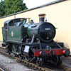
After waiting ages for the post to deliver some crankpin nuts I have managed to complete the conversion of a Loco to P4 gauge. There were several hick ups involved but all seems to be well even if it has but 50cms of track to run on!
In the background is the incline being constructed for the road to Coleford from Coleford Junction ( This being the proper Coleford in the FOD and not Rotherham or the Barnstaple line!). As in my previous civil engineering projects I am using 5mm ply with honeycombe type under frames. As this is the first time I have worked to a plan the elevated work will be completed first (it demands 13M run from the Juction through Coleford S&W and then on down to Whitecliff lime burning plant through the convenient tunnel). It also enables the OO track system to co-exist until stock gets converted.
The Gibsons delivery coincided with jeremys offerings (the last order went AWOL) so I now have some more rail to play with but it looks as if I shall have to order well in advance to keep up with my ambitions (and before we push off to Spain to miss the worst of the winter)
You do not have the required permissions to view the files attached to this post.
Who is online
Users browsing this forum: ClaudeBot and 0 guests