SCC - Sparkshot Custom Creations

If you are making something new or have found something, announce it here.
User avatar
Knuckles
Posts: 1262
Joined: Fri Nov 18, 2011 9:15 pm

Re: SCC - Sparkshot Custom Creations

Postby Knuckles » Sun Dec 20, 2015 4:15 pm

nberrington wrote:This might be a dumb question - is it possible to print the chassis as rhodium plated or raw bronze? Or would that just be too expensive?


I've just looked for you. The Rhodium plated and Brass (EDIT: Sorry you said Bronze - same issue though) materials won't print any of the chassis due to the bounding box being too big. In other words they haven't enough space apparently. :?

I could get you one fixed up in Stainless Steel with a bit of thickening up in places but looking at it, after I've added a bit for me it'd cost you around £40-60 depending what it was. :shock:
If you want one I'll get you one though. :?

EDIT 2: The above is for loco chassis.

For tender chassis Rhodium is already a green tick pass so if you want one then I'll make it an option. :thumb
Will be over £100 though so not brilliant! :shock:

Brass and bronze will pass after a little thickening in areas.

EDIT 3: If you want a tender chassis in Platinum it'll cost you around £6,000! LOL.


To everyone, there is a big post on the previous page.
Last edited by Knuckles on Sun Dec 20, 2015 4:25 pm, edited 4 times in total.
“He who dares not offend cannot be honest.” Thomas Paine

https://www.sparkshotcustomcreations.com/
Mostly 3D Printed Loco kits etc.

SCC Price list (7/4/22)
https://www.sparkshotcustomcreations.co ... e77d42.pdf

User avatar
Noel
Posts: 1982
Joined: Wed Jun 23, 2010 1:04 pm

Re: SCC - Sparkshot Custom Creations

Postby Noel » Sun Dec 20, 2015 4:20 pm

Knuckles wrote:if the top of the axles holes had a hole drilled through them in effect being the 'pockets' spoken about and a working buffer spring housed inside and capped at the top, would it be ok on top of a loose bush bearing (that may spin occasionally I'd think)? I'd imagine it'd be bodge engineering but as it would only protrude downwards a maximum of 1mm I doubt it'd snag or cut the bush to bits.


I'm no engineer, Knuckles, but if I understand you correctly, I think there is a problem here. If the bearing is round and loose in the frame, friction will ensure that it will try to rotate when the axle does, as the bearing will have no restraint, so I think spin will be more than just occasional. That means that the weight of the loco will be resting effectively on whatever small surfaces each spring has in contact with the bearing. I suspect peculiar wear patterns will be the result, with a risk that the spring will distort sideways [even with just 1mm protrusion] and jam.

Noel
Regards
Noel

User avatar
Knuckles
Posts: 1262
Joined: Fri Nov 18, 2011 9:15 pm

Re: SCC - Sparkshot Custom Creations

Postby Knuckles » Sun Dec 20, 2015 4:27 pm

Noel wrote:
Knuckles wrote:if the top of the axles holes had a hole drilled through them in effect being the 'pockets' spoken about and a working buffer spring housed inside and capped at the top, would it be ok on top of a loose bush bearing (that may spin occasionally I'd think)? I'd imagine it'd be bodge engineering but as it would only protrude downwards a maximum of 1mm I doubt it'd snag or cut the bush to bits.


I'm no engineer, Knuckles, but if I understand you correctly, I think there is a problem here. If the bearing is round and loose in the frame, friction will ensure that it will try to rotate when the axle does, as the bearing will have no restraint, so I think spin will be more than just occasional. That means that the weight of the loco will be resting effectively on whatever small surfaces each spring has in contact with the bearing. I suspect peculiar wear patterns will be the result, with a risk that the spring will distort sideways [even with just 1mm protrusion] and jam.

Noel


Yeah this is what was going through my mind. I was thinking that with such a small protrusion it might be ok.

Ok scrap that, proper horn blocks.
“He who dares not offend cannot be honest.” Thomas Paine

https://www.sparkshotcustomcreations.com/
Mostly 3D Printed Loco kits etc.

SCC Price list (7/4/22)
https://www.sparkshotcustomcreations.co ... e77d42.pdf

David Knight
Posts: 820
Joined: Sun Jul 20, 2008 6:02 pm

Re: SCC - Sparkshot Custom Creations

Postby David Knight » Sun Dec 20, 2015 6:47 pm

Knuckles wrote "How would I go about doing as you suggest? I very much like the idea of doing something for a railway society (Scalefour Society? :idea: ) as it'd no doubt have more coverage that way."

Well, here's a starting point http://www.scalefour.org/links/prototype.html. I suspect that members of the societies may well beat a path to your door once word gets out that you do commissions of obscure prototypes ;) . Doubtless there are members within our own group who will start discussions but to cast a wider net you would either need to contact the societies directly or post something specific on the likes of RMweb with particulars as to what they need to bring to the table in the way of information and for your part times and costs. I'm sure there are other much wiser heads than mine in this matter but that's my two pennorth.

Cheers,

David

Philip Hall
Posts: 1953
Joined: Mon Aug 10, 2009 7:49 pm

Re: SCC - Sparkshot Custom Creations

Postby Philip Hall » Sun Dec 20, 2015 6:49 pm

Back to back EM standard is 16.5mm but Ultrascale and Alan Gibson are often set to 16.7, maybe a bit more, as the flanges are thinner than when the standard was established a long time ago. For this reason Markits wheels, even the RP25 ones, usually come out at 16.5mm, as they have much thicker flanges. For EM I would say 15mm frames overall as an absolute maximum, 14.5mm would allow for a little more 'wriggle room', side play etc. I doubt you'll find this in any EM standards document, but I might be wrong!

I also agree that a round bearing will tend to revolve in a frame, and to do so in a plastic frame is asking for trouble, however stable and hard the material is. A square bearing sliding in a metal hornguide is the only relatively wear free option. If the hornblock were to be arranged to slide in a plastic frame there would still be wear, and also I don't think that it would slide freely enough. Could I also throw in a thought that many plastics react badly to oil. The types our wheels are made of are usually impervious so long as you are careful to use a plastics friendly oil, but do you have any information that the plastics you are printing are resistant to oil? Otherwise the frames might not last, simply because oil will travel, however careful you are to contain it!

Philip
Last edited by Philip Hall on Mon Dec 21, 2015 12:09 am, edited 1 time in total.

User avatar
Knuckles
Posts: 1262
Joined: Fri Nov 18, 2011 9:15 pm

Re: SCC - Sparkshot Custom Creations

Postby Knuckles » Sun Dec 20, 2015 8:40 pm

David Knight wrote:Knuckles wrote "How would I go about doing as you suggest? I very much like the idea of doing something for a railway society (Scalefour Society? :idea: ) as it'd no doubt have more coverage that way."

Well, here's a starting point http://www.scalefour.org/links/prototype.html. I suspect that members of the societies may well beat a path to your door once word gets out that you do commissions of obscure prototypes ;) . Doubtless there are members within our own group who will start discussions but to cast a wider net you would either need to contact the societies directly or post something specific on the likes of RMweb with particulars as to what they need to bring to the table in the way of information and for your part times and costs. I'm sure there are other much wiser heads than mine in this matter but that's my two pennorth.

Cheers,

David


This is all sounding very interesting. :)

Will be doing more thinking first me thinks. Thanks again.

Philip Hall wrote:Back to back EM standard is 16.5mm but Ultrascale and Alan Gibson are often set to 16.7, maybe a bit more, as the flanges are thinner than when the standard was established a long time ago. For this reason Markits wheels, even the RP25 ones, usually come out at 16.5mm, as they have much thicker flanges. For EM I would say 15mm frames overall as an absolute maximum, 14.5mm would allow for a little more 'wriggle room', side play etc. I doubt you'll find this in any EM standards document, but I might be wrong!

I also agree that a round bearing will tend to revolve in a frame, and to do so in a plastic frame is asking for trouble, however stable and hard the material is. A square bearing sliding in a metal hornguide is the only relatively wear free option. If the hornblock were to be arranged to slide in a plastic frame there would still be wear, and also I don't think that it would slide freely enough. Could I also throw in a thought that many plastics react badly to oil. The types our wheels are made of are usually impervious so long as you are careful to use a plastics friendly oil, but do you have any information that the plastics you are printing are resistant to oil? Otherwise the frames might not last, simply because oil will travel, however careful,you are to contain it!

Philip


I found the Back to back info but as you implied the EM widths seem to not have a standard. 14.5 sounds good. I'll make the 3D planning wheel sets as I usually do and see how things align.

The oil issue isn't anything I can do anything about but I'm sure with preparation and the right primers ans varnishes protective layers can be added.

Here is the Shapeways information regarding your concerns...

http://www.shapeways.com/materials/stro ... tic?li=nav

&

http://www.shapeways.com/materials/fros ... tic?li=nav
Anoyingly some parts of Shapeways say FUD & FXD are Plastic and other parts say it is Resin. Oh well. I call it resin as it looks, feels and behaves like it.


EDIT: Forgot to say, if the horn carriers are glued fastly in place then there will be no friction on the plastic. As the block itself will slide in the metal carriers.
“He who dares not offend cannot be honest.” Thomas Paine

https://www.sparkshotcustomcreations.com/
Mostly 3D Printed Loco kits etc.

SCC Price list (7/4/22)
https://www.sparkshotcustomcreations.co ... e77d42.pdf

User avatar
Ian Everett
Posts: 379
Joined: Tue Jul 21, 2009 9:43 pm

Re: SCC - Sparkshot Custom Creations

Postby Ian Everett » Sun Dec 20, 2015 11:32 pm

Knuckles wrote:
(a lot of sense with which I agree.)

Ok scrap that, proper horn blocks.


Not necessarily. How about a small plunger, like a Gibson sprung pick-up, with a rod which fits inside the spring and an end which is the same outside diameter as the spring and is a sliding fit within the pocket?

Ian

User avatar
Knuckles
Posts: 1262
Joined: Fri Nov 18, 2011 9:15 pm

Re: SCC - Sparkshot Custom Creations

Postby Knuckles » Mon Dec 21, 2015 5:11 am

Makes sense. Whatever I end up doing needs to be easily replicated by everyone though. If I every sell full kits in a box one day that'd be different but while just on Shapeways it really needs to be something easy and simply brought.
“He who dares not offend cannot be honest.” Thomas Paine

https://www.sparkshotcustomcreations.com/
Mostly 3D Printed Loco kits etc.

SCC Price list (7/4/22)
https://www.sparkshotcustomcreations.co ... e77d42.pdf

garethashenden
Posts: 406
Joined: Tue Apr 07, 2015 9:41 pm

Re: SCC - Sparkshot Custom Creations

Postby garethashenden » Mon Dec 21, 2015 5:27 pm

I think in this situation compensation may be easier than springing. I know springing gives a smoother ride, but it's a lot harder to print.

My thought would be to have a fixed rear (or front) axle and the other two with twin beam compensation. You can print curved slots for the bearings to move in as well as the beams to hold the bearings. I drew this up quickly to show what I meant, the slots are probably a lot longer than they need to be, but it shows the curve more. If they're straight the beams won't be able to pivot.

Image

User avatar
Knuckles
Posts: 1262
Joined: Fri Nov 18, 2011 9:15 pm

Re: SCC - Sparkshot Custom Creations

Postby Knuckles » Mon Dec 21, 2015 6:42 pm

Another good idea. Thanks for the drawing. Drawing the kidney dish shaped holes correctly will be easy. If I'm not mistaken I'd just find the exact middle between the two axle centres and a pull a circle out from there to the centre of one of the axles - then draw the curved bush hole. That's fine, but how would a modeller then go about the bar? I assume that'd be a scratch build project?

Back to a springing idea, if I removed the dummy horn-blocks then you could in theory bung some real ones in. The only potential issue I see is sorting out the springing itself.
“He who dares not offend cannot be honest.” Thomas Paine

https://www.sparkshotcustomcreations.com/
Mostly 3D Printed Loco kits etc.

SCC Price list (7/4/22)
https://www.sparkshotcustomcreations.co ... e77d42.pdf

dal-t
Posts: 654
Joined: Mon Jan 11, 2010 8:06 pm

Re: SCC - Sparkshot Custom Creations

Postby dal-t » Mon Dec 21, 2015 7:51 pm

Knuckles wrote:
Back to a springing idea, if I removed the dummy horn-blocks then you could in theory bung some real ones in. The only potential issue I see is sorting out the springing itself.


A more fundamental issue may be how to do the 'bunging in', or more accurately the retaining once 'bunged'. I assume no-one would attempt to solder hornblock guides to the plastic! ( ... interesting aromas and a very sticky mess if they do) - but does WSF take cyano, because most nylons I've known don't, or only do so (very) badly? I know you can superglue FUD, but I'm still unclear whether that makes it more liable to shatter, having had a couple of pieces disintegrate on me while attempting to fix them in place. A couple of buffer guides gone west is just about bearable; I suspect most people would view a chassis reduced to a pile of dust somewhat differently.
David L-T

garethashenden
Posts: 406
Joined: Tue Apr 07, 2015 9:41 pm

Re: SCC - Sparkshot Custom Creations

Postby garethashenden » Mon Dec 21, 2015 7:57 pm

Knuckles wrote:Another good idea. Thanks for the drawing. Drawing the kidney dish shaped holes correctly will be easy. If I'm not mistaken I'd just find the exact middle between the two axle centres and a pull a circle out from there to the centre of one of the axles - then draw the curved bush hole. That's fine, but how would a modeller then go about the bar? I assume that'd be a scratch build project?


I had assumed that you would draw up two bars and add them to the print. You'll want to size the whole so that 1/8" top hat bearings fit in the bars and can be glued in place. They outside of the bearing needs to be able to slide in the frames. All I'd expect the modeller to provide is 0.5 or 1mm brass rod for the bars to pivot on.

User avatar
Knuckles
Posts: 1262
Joined: Fri Nov 18, 2011 9:15 pm

Re: SCC - Sparkshot Custom Creations

Postby Knuckles » Mon Dec 21, 2015 10:51 pm

WSF and Cyno' work nicely. I've been using the conbo throughout with ease. I'm a big fan of Powerbond 806 and Haffix - worth the extra spondoolies in my opinion but so far on the WSF I've only been using el cheapo get 10 tubes for a quid stuff. I think it is because the WSF is porous. I haven't tried Araldite epoxy or anything else yet.


I am unsure what you mean by the brass rod and things, could you tephrase please?
Last edited by Knuckles on Tue Dec 22, 2015 9:58 am, edited 1 time in total.
“He who dares not offend cannot be honest.” Thomas Paine

https://www.sparkshotcustomcreations.com/
Mostly 3D Printed Loco kits etc.

SCC Price list (7/4/22)
https://www.sparkshotcustomcreations.co ... e77d42.pdf

garethashenden
Posts: 406
Joined: Tue Apr 07, 2015 9:41 pm

Re: SCC - Sparkshot Custom Creations

Postby garethashenden » Mon Dec 21, 2015 11:43 pm

A picture's worth a thousand words...
Image

There are two beams pivoting on a brass rod.

User avatar
jon price
Posts: 641
Joined: Mon Jun 07, 2010 2:34 pm

Re: SCC - Sparkshot Custom Creations

Postby jon price » Tue Dec 22, 2015 12:20 am

with the bearings inboard of the chassis on the compensation beams how do you stop the wheels wobbling back and forth and rubbing against the outer frames? Looks to me like fibre washers would bind on the holes in the outer frames.
Connah's Quay Workshop threads: viewforum.php?f=125

User avatar
Knuckles
Posts: 1262
Joined: Fri Nov 18, 2011 9:15 pm

Re: SCC - Sparkshot Custom Creations

Postby Knuckles » Wed Dec 23, 2015 4:53 pm

Hi guys.

I could do with your collective help again if possible.

Someone on RMweb (is he here too?) asked me if I could do a modification of the K2 into the earlier Cambrian 4-4-0, and seeing as it would in effect be another loco to the range with less work I decided yes. Think I'd be silly not too. Anyway, there is a wee problem...

One scale drawing says the cab side sheet profile is shape 'A' and the others say shape 'B.' Photographs seem to suggest A but then again is it a detail variation and they both existed? You get this with scale drawings, one saying one and another saying another.

I made this small collage...

http://i86.photobucket.com/albums/k112/ ... undrum.png

The other issue is one drawing reckons the bogey wheels should be 6" (2mm's) wider in diameter and the PDF booklet seems to not mention it and have the wheels the same size.

Oh boy.

Any ideas?
“He who dares not offend cannot be honest.” Thomas Paine

https://www.sparkshotcustomcreations.com/
Mostly 3D Printed Loco kits etc.

SCC Price list (7/4/22)
https://www.sparkshotcustomcreations.co ... e77d42.pdf

dal-t
Posts: 654
Joined: Mon Jan 11, 2010 8:06 pm

Re: SCC - Sparkshot Custom Creations

Postby dal-t » Wed Dec 23, 2015 5:21 pm

Have you tried asking the Cambrian Company Steward of the HMRS (here)? That ought to provide the authoritative answer ...
David L-T

User avatar
Knuckles
Posts: 1262
Joined: Fri Nov 18, 2011 9:15 pm

Re: SCC - Sparkshot Custom Creations

Postby Knuckles » Wed Dec 23, 2015 6:39 pm

Okies, many thanks.

I've scrolled through all the menu's and sent an email to the 'early railways' section.

For interest (or help here if anyone knows) I'll paste what I wrote...


Hello, I've made a scale model of a Furness K2 and released it as a kit here...
http://www.shapeways.com/shops/sparksho ... eationsscc

The problem is I'm now converting another one into the earlier Cambrian Loco. I've already converted it to right hand drive but there seems to be two major difficulties regarding scale drawings. The first issue is presented in this picture that I made and sent to the one who requested for the modification regarding the cab sheet profile...

http://i86.photobucket.com/albums/k112/ ... undrum.png

I hope you can see my dilemma!

The other problem is the bogey wheels; my data PDF said the Furness K2 bogey wheel diameter is 3 foot diameter - all well and good.

The scale drawings of the Cambrian locomotive say they are 3 foot 6 inches diameter - OK so a difference apparently.

The PDF document lists the main differences between the earlier Cambrian loco and the Furness K2's but fails to mention the change in bogey wheel size that I would have expected, yet to make matters worse the drawing of the K2 in the same document (Phoenix super heated in this case) has 3 foot 6 inches diameter bogey wheels too when they should be 3 foot.

So as you can imagine progress has halted badly due the need to get this right.

If you could at all help with these two issues I'd be highly grateful.
Many thanks in advance. :)
“He who dares not offend cannot be honest.” Thomas Paine

https://www.sparkshotcustomcreations.com/
Mostly 3D Printed Loco kits etc.

SCC Price list (7/4/22)
https://www.sparkshotcustomcreations.co ... e77d42.pdf

essdee
Posts: 554
Joined: Sat Nov 29, 2008 4:47 pm

Re: SCC - Sparkshot Custom Creations

Postby essdee » Wed Dec 23, 2015 6:59 pm

Gavin,

Sorry I cannot help with the Cambrian 4-4-0 query. However, although 'deep in the trenches' at present, I just wanted to emerge briefly to raise my hat to you, for the formidable amount of work you have undertaken on all this, during this past year, and I sincerely hope it earns you appropriate rewards. Keep up the good work! A more refined finish to the currently-available print materials must surely come, at a reasonable price, in due course? Keep pushing at that envelope, man.........

One thought for you. With these small pre-Group designs, and our usage of them on sharper-than-prototype curves, very probably hauling (admittedly relatively short) trains incorporating a number of heavy etched or cast vehicles, there are likely to be haulage issues to contend with, even with pinpoint axle ends. The inherent lightness and thickness of printed materials are likely to conspire here, to hinder getting enough weight on to the drivers. To that end, I would be strongly inclined to install a motor in the tender, with a shaft to the gearbox on the loco's leading axle. I have spent much of the last two years wangling such drives into pre-Group 0-6-0 and small-boiler 4-6-0 designs, and am now confident of this approach, using Chris Gibbon's High Level Kits 'TendeRiser' 1:1 step-down gearbox to drop the drive shaft below cab floor level. This will allow critical extra weight to be inserted where the motor would otherwise be, above the drivers. You may want to bear this in mind when you lay out your designs for printed bodies?

I look forward to further developments - will you be bringing examples to Scalefour North in April (he asked, hopefully)?

Have a really Great Christmas and a rewarding New Year in 2016 - you deserve it!

Best wishes,

Steve

User avatar
Knuckles
Posts: 1262
Joined: Fri Nov 18, 2011 9:15 pm

Re: SCC - Sparkshot Custom Creations

Postby Knuckles » Wed Dec 23, 2015 8:08 pm

Sweet. Many thanks for such kind and encouraging reply, :thumb

If you can't help with the wheel issue then no worries, thanks for having a look though.

I agree that the current prices for the best materials are stupidly high. I'm annoyed with the pricing of Shapeways FUD resin because it is not in my or many people's opinion good. That's putting it more than lightly but at the moment I feel powerless to do much about it other than saving for a printer...which I am doing. In the example vid I used the cheapest and roughest material because A it was cheaper to do the testing and B hopefully I've shown it is possible to get an acceptable finish with some effort...but there is no denying the FUD is better...just so bloody expensive and that's before adding a small cut on top. :(

Anyway, hoefully what you said is the future and prices can drop, it really needs to.

I haven't ever used a tender extender but I can see the sense in it. The test builds used small gearboxes and motors to avoid hacking away at the firebox and boiler and to basically show me (and everyone via video) that they can be made in go working models. They were a wee on the weak side though, but that was expected. The K2 has a flywheel in and that makes it run so much sweeter.

I think I might try a tender extender for the next tender loco I do and see how it goes. I could make a series of posts on it too, hopefully making an interesting feature. Currently as I have never handled the unit you describe I'm unsure what modifications the tender would entail but what I can say is I designed them to have the tops removable thus providing access the the insides to add weight or DCC chips/speakers.....and now a motor maybe.

I will likely be at S4 North. I have missed the last 2 or 3 events for various reasons so I am definetly needing and wanting to, I can only come on the Sundays though. If Danny and gang would want/allow it I could leave the models with them whilst I bimble and collect them at the end, but that consideration is something for later and not fully up to me.

Again, many thanks for the reply. I would wish you a Merry Christmas and 'New Year' (isn't the New Year!) but it's something I don't do now as I stopped celebrating it (as it now conflicts with my beliefs) once I dug hard into its origins and past...but that's a subject only those who care enough usually dare venture! Very unpopular to say I know, oh well. :?

Have a good month instead!

And again many thanks for the advice. :thumb
“He who dares not offend cannot be honest.” Thomas Paine

https://www.sparkshotcustomcreations.com/
Mostly 3D Printed Loco kits etc.

SCC Price list (7/4/22)
https://www.sparkshotcustomcreations.co ... e77d42.pdf

essdee
Posts: 554
Joined: Sat Nov 29, 2008 4:47 pm

Re: SCC - Sparkshot Custom Creations

Postby essdee » Wed Dec 23, 2015 11:11 pm

Gavin,

'No probs' -as they say......!

After the festives have subsided, I will PM you with some pics of the motor/gearboxes I have been installing, to help you assess how it might impinge on what you are doing. A picture speaks a thousand words etc. I was initially daunted, but having dived in and swum around a bit, the water seems rather warmer.

Good sense to practise using the cheaper material! You are ahead of me on understanding all but the basic differences of the materials involved - but you are working in a rapidly-evolving field.

Enjoy your winter break, whatever and however!

All best

Steve

User avatar
Knuckles
Posts: 1262
Joined: Fri Nov 18, 2011 9:15 pm

Re: SCC - Sparkshot Custom Creations

Postby Knuckles » Thu Dec 24, 2015 7:27 pm

essdee wrote:Gavin,

'No probs' -as they say......!

After the festives have subsided, I will PM you with some pics of the motor/gearboxes I have been installing, to help you assess how it might impinge on what you are doing. A picture speaks a thousand words etc. I was initially daunted, but having dived in and swum around a bit, the water seems rather warmer.

Good sense to practise using the cheaper material! You are ahead of me on understanding all but the basic differences of the materials involved - but you are working in a rapidly-evolving field.

Enjoy your winter break, whatever and however!

All best

Steve


Thanks Steve. I look forward to seeing them. :thumb I did buy some FUD too but mostly WSF for engine bodies as it's cheaper. Dimensionally they are the same.

I don't know who it interests but as you all know now, I'm converting one of my K2's into the earlier Cambrian Class 61's so I thought I'd give a wee progress report.

The cab side profile has been changed, the spectacle plates/windows are now smaller and moved position, the whole thing is perfectly mirrored to make it RHD, the internal cab splashers have a lip around them now.

The chassis has been modified heavily to now be used with the 3' 6" bogey wheels instead of the 3' ones (Bum - was hoping to not have to!) and I'm not far from it being done. ((He says)
3D meshes are like model railways, you think you finished one but you can always improve it.)
“He who dares not offend cannot be honest.” Thomas Paine

https://www.sparkshotcustomcreations.com/
Mostly 3D Printed Loco kits etc.

SCC Price list (7/4/22)
https://www.sparkshotcustomcreations.co ... e77d42.pdf

User avatar
Knuckles
Posts: 1262
Joined: Fri Nov 18, 2011 9:15 pm

Re: SCC - Sparkshot Custom Creations

Postby Knuckles » Wed Dec 30, 2015 8:01 pm

Ok little progress update. Before I start please bear in mind I can always revert back to the original profile and size both for the body and the chassis. The conflicting data is a pain but we'll get there.

But for now I've spent all day redoing the chassis and body.

The Furness K2 kit has been designed with a wheelbase of 5’ 9” + 6’ 8” + 8’ 6” with 3' Bogey wheels, as a comparison the Cambrian that is being Kit-bashed from it in 3D (So you don't have to!)now has the current spec...


Right Hand Drive.
Different Cab side profile and roof, Optional Jack sprued under the cab (Seen between driving wheels sometimes).


Cambrian Class 61 chassis now has 3' 6" bogey wheels, a wheelbase of 5’ 6” + 6’ 6½” + 8’ 3” (Can change if evidence kills it).

The front driving splasher has been moved forward to fit the new wheelbase, as has the whole rear section evidenced by the join mark.

Locomotive works, converting a Furness K2 into a Cambrian Class 61, only thing missing is the cranes! In reality it was more like the reverse but never mind. (This pic shows Left Hand Drive I know)
Image

Join mark visible, as is the bigger bogeys.
Image

Top picture is the Cambrian before I fiddled today, bottom the new. If you look at the splashers the bottom front driver is forward a bit, the rear section however has been shuffled forward quite a bit, as a result the new version is now about a scale 18 inches shorter.
Image

Here is the same thing without all the horrid polygon wire lines everywhere.
Image

Hope you found that interesting. :)

As I said I can revert things and if you have the info that'd be sweet but I do think the evidence goes in this direction mostly. I ask you all because together we all pool knowledge and hopefully get the correct outcome.
Last edited by Knuckles on Tue Feb 16, 2016 7:52 pm, edited 1 time in total.
“He who dares not offend cannot be honest.” Thomas Paine

https://www.sparkshotcustomcreations.com/
Mostly 3D Printed Loco kits etc.

SCC Price list (7/4/22)
https://www.sparkshotcustomcreations.co ... e77d42.pdf

User avatar
Knuckles
Posts: 1262
Joined: Fri Nov 18, 2011 9:15 pm

Re: SCC - Sparkshot Custom Creations

Postby Knuckles » Thu Dec 31, 2015 7:08 am

Ok fellow modellers.

I had an idea and implemented it. It is an idea that I have done similar before.

Now please note, if you have been following this thread you know the controversy and that I want to get things right.

To make things clearer here are the problems:

A) - Different Scale Drawings and text from different sources give different wheelbases and different sizes. These being...
- 3' bogey wheels or 3'6" ?
- Conflicting wheelbases for the Cambrian of
5’ 6” + 6’ 6½” + 8’ 3”
or 5' 9" + 6' 6" + 8'6"
and the Furness K2 being
5’ 9” + 6’ 8” + 8’ 6”
- Some sources and people are saying the two locomotives shared the exact same wheelbase, others not.


B) - These may be genuine variations that existed, or some information may clearly be wrong. Hard to know for sure. Awkward as there were a few builders and if there were variations this may be a reason.

C) - We (me included) tend to believe that the info we have is correct and everyone else is wrong. Your scale drawing or railway book is
king, bugger the rest! With confliction how do you know yours is right?

D) - Did the Furness K2 (21 Class) that came after the Cambrian 61 change any wheel sizes or wheelbase?

E) - If so repeat point A & B for the K2.

--------------

So, I'm still trying to get the bottom of this and I have done something interesting.

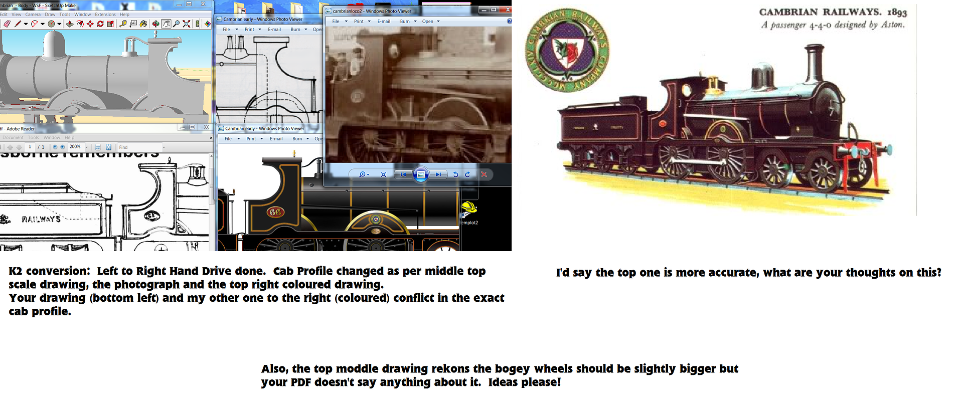
As a disclaimer I know that the prototype photograph of the Cambrian loco is not perfectly sideways, neither can it be due to the reality
of perspectives changing, neither can the following be considered 100% accurate, however, I've been as careful and exacting as I can going only by this photograph. Many thanks to Quarryscapes for providing it...

Image

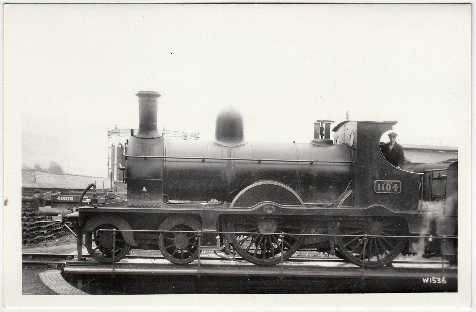
So with that I have to the best of my ability found the axle centre of the wheels and from the front driving wheel drew horizontal lines either side. This gives us the best approximation of 6 feet. Then a circle was drew around it as best as can be done with a less than perfect angle due to perspective shift.

The bogey wheels from the top centre have a line horizontal right towards the undisputed 6 foot driving wheel - as you can see this particular bogey is 3 foot 6 inches. No arguing there.

From the 6 foot horizontal line previously mentioned that red line was copied and pasted, converted blue and divided into 6 to represent individual feet. 3 extra feet were added based on copying and pasting effectually creating a Rule/Ruler. Again, I know the perspective shifts but this exercise is to try to establish what matches what data best based on this photograph.

By placing the rule at the key areas and referring to the 3 disputed wheelbases we can see what matches best and draw some conclusions.

Image

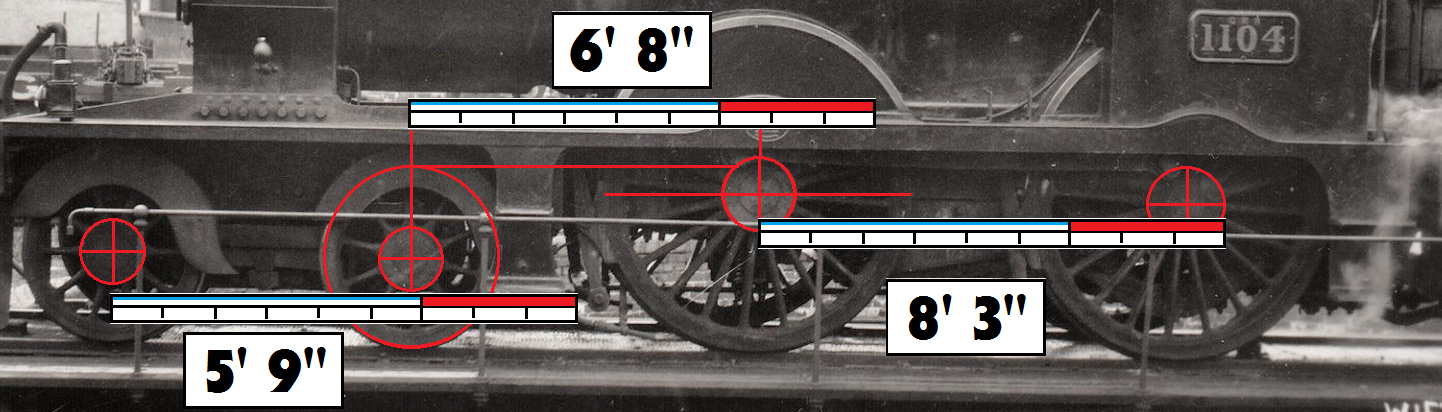
According to this picture then, I estimate the wheelbase to be

5’ 9” + 6’ 8” + 8’ 3”

Which is different to ALL the 3 above! It matches one wheelbase only lest for the value of 8'6".

So, conclusion & Questions:

A) - If the above exercise is good enough to go by (seems clear to me) then we have a 4th wheelbase that may be the median truth. If it is wrong then the wheelbase of 5’ 9” + 6’ 8” + 8’ 6” must be correct instead - I'm thinking this is likely. The far right perspective may skew the 3 inches out of scale.
B) - If this new wheelbase is correct then is it across the board for ALL the Class 61's or were there indeed variations?
C) - Did these dimensions transfer into the Furness K2 or is the K2 indeed different?
D) - If they did transfer and the K2 is the same, was the K2 fixed or did that have genuine variation?

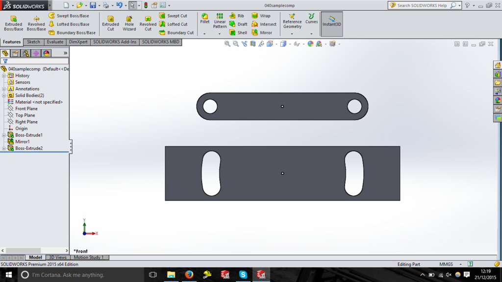
Model Considerations: The Furness K2 that is available has been built with a wheelbase of
5’ 9” + 6’ 8” + 8’ 6”

This exercise shows the wheelbase to be 5’ 9” + 6’ 8” + 8’ 3” or the same if the right hand value is perspective skewed too much.

The K2 model has been designed to use the 3' wheels not the 3' 6" but if you want bigger wheels this can easily be changed by filing a little extra clearance for the bogeys and when I upload them (if you want to) getting the bigger bogey splashers. The chassis meshes can always be altered to take the bigger wheels if necessary although if this post is true the then wheelbase can stay. BUT - does the K2 indeed have bigger bogey wheels? This is still to be answered.

For the Cambrian I'm likely to use the older model that is a wee longer based on this but again I'm straining to find the truth and I think I may have found some.


Thoughts please? :)


Additional Issue: For the tender I have different sources with different wheelbases too. So far it is a toss up between 6' 3", 6'6", and 6' perfectly. The model is 6' 3" but currently on hold due to these issues.


The model is designed with the 3'6" tender wheels, but other sources are saying 3'10" and another even larger than 3'6" so I'm drinking whisky.
“He who dares not offend cannot be honest.” Thomas Paine

https://www.sparkshotcustomcreations.com/
Mostly 3D Printed Loco kits etc.

SCC Price list (7/4/22)
https://www.sparkshotcustomcreations.co ... e77d42.pdf

andrewnummelin
Posts: 374
Joined: Mon Jul 21, 2008 9:43 am

Re: SCC - Sparkshot Custom Creations

Postby andrewnummelin » Thu Dec 31, 2015 9:26 am

Mention of this thread has been made on the Welsh Railways Research Circle forum where I posted:
-----------
For definitive information on the Furness locos one may care to note that the HMRS lists a general arrangement drawing:
http://www.hmrs.org.uk/drawings/drawing ... p?id=17680
It's a shame they don't have the same for the Cambrian! But they do have drawings of the small bogie and the large Belpaire passenger classes.
-------------

Doesn't help with the discussion on the Cambrian version, but may be useful for anyone wanting to add more detail to the Furness one.........always assuming that the real loco and the official drawing actually matched.
Regards,

Andrew Nummelin


Return to “New Products”

Who is online

Users browsing this forum: ClaudeBot and 2 guests