I think the short answer to your question Tim is "yes".
I know Terry is busy with lots of things so, without wishing to hi-jack his thread, perhaps I can give a bit of an intro to how this project came about and some of the "design principles" behind it. I can also post a few photos to which Terry can then add his own and his experience of putting the job together.
Firstly, as many here will know, for my own "Minories" layout, I built a 25 lever interlocked frame based around the SHAG frame which has been available from the stores for many years now. It is very nice and bar far the best available on the market at reasonable cost. However, it was never designed to have locking fitted, and although the finished job works well enough, it was a bit of a tussle to get it all to work nicely. Also, because of the way the 5-lever modules assembled together, it was not really suitable for "long" frames. Some years ago therefore I suggested that I might redesign it keep its basic features whilst addressing these shortcomings. That is as far as it it got until last year, I got involved with Jon Elliot's "Leeds City" layout - as described in the RMWeb thread above, and "volunteered to look at a mechanically locked frame (or two). This provided the necessary impetus to get on with the job.
The main issues needing to be tackled were these:-
For Locking:-
- improved accuracy to ensure reliability of the locking
- fixing to allow the locking table to be built up separately then bolted in place
- improved catch handle mechanism
- ability to fit and remove levers after the frame and locking have been assembled
For long frames:-
- ability to fit and remove levers for painting etc
- ability to join together and split apart 5-lever modules without any loss of accuracy of pitch
- means of fitting / removing electricl switches with breaking down the whole frame
To address some shortcomings in the existing design which those who have built them will have encountered
- the lack of "self-jigging" in the main frame
- the lever slots etched a bit too narrow (and a pain to open out!
- the need to make "spacer tubes" to space and align the levers along the pivot rod.
- the need to have one lever pivot rod the full length of the frame
The extent to which these objectives are both valid and have been achieved will be for others to say of course!
I should say that I have done my best to maintain full compatibility with the original frame in terms of appearance, dimensions "feel" etc. - you can put them side by side and they are hard to tell apart at a glance. Also, the locking - which will also be available from the stores - can still be fitted to the existing frame design - though it is a bit of a knife and fork job. So anyone half-way through building an existing frame is catered for.
Here are a few photos to show the "new" by comparison with the "original:-
Lever Frame.jpg
And my attempt at "improvement"
prototype.jpg
The main things to notice are that the frame folds up in one piece and there is a base-plate which accommodates the pivot rod and spaces the levers out accurately. There are also various fixing holes to allow these five lever models to be joined and slit using nuts and bolts. Obviously, by splitting the five lever modes, the pivot rod can be slid out and the levers withdrawn from the top.
I have also added a slightly more sophisticated means of taking off a mechanical drive for both points and signals
Mech Drive Take off 1.jpg
I have also changed the way the electrical switches are fitted to place them outside the frame - this takes up more space, but it does mean that if - nay, when - a switch goes down on you, you have the possibility to replace it without having to break down the whole frame.
prototype 2.jpg
In terms of adding the locking (which has been developed based on experience of the Minories version), various fixing points have been created to allow nut and bolt assembly
Rear Cam Guide.jpg
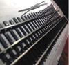
The upshot of all this is that the locking can be built and tested as unit on the bench, then each five-lever frame unit bolted on and the levers added:-
Assembling Frames.jpg
Hopefully, that will give people a bit of an idea what it is all about, and prepare the background for Terry's experience of having to build the bloomin' things!
EDIT:- the link above does not work but this hopefully will:-
http://www.rmweb.co.uk/community/index. ... try3108167You do not have the required permissions to view the files attached to this post.