I'm now at the point where I'm wiring my first turnout. The relevant rails on the turnout have been bonded, power is being fed from the heel of the turnout and the two diverging roads are isolated from the turnout and have their own power connections. I've not added any wiring to change the frog polarity at all and my test loco is able to run across the turnout and take either road with no problems.
So, if you'll excuse my ignorance, is it necessary to add wiring to change the frog polarity or would this only be necessary if the diverging roads were not electrically isolated from the turnout?
John
Changing frog polarity...
-
John Donnelly

- Web Team
- Posts: 1092
- Joined: Fri Mar 16, 2012 7:03 pm
-
nigelcliffe
- Posts: 751
- Joined: Mon Jul 21, 2008 8:31 am
Re: Changing frog polarity...
Your current arrangement (no connection to the frog) has created a "dead frog" turnout, with a fairly long "dead" part. Given locos of long enough wheelbase, and enough wheels picking up, they will run over this (as you have found). But, a shorter wheelbase loco, or a problem picking up, might lead to locos stalling on the dead section.
So, I'd fit some sort of feed to the crossing (frog) and arrange for it to be switched when the turnout is moved. How it is switched depends on how the turnout blades are moved; what I might use for mechanical movement would be different to that with turnout motors or servo motors.
- Nigel
So, I'd fit some sort of feed to the crossing (frog) and arrange for it to be switched when the turnout is moved. How it is switched depends on how the turnout blades are moved; what I might use for mechanical movement would be different to that with turnout motors or servo motors.
- Nigel
Nigel Cliffe - Blog of various mostly model making topics
-
grovenor-2685

- Forum Team
- Posts: 3923
- Joined: Sun Jun 29, 2008 8:02 pm
Re: Changing frog polarity...
John,
You may or may not have created a dead frog, that depends on where in the turnout you have left insulating gaps and which are the 'relevant' rails that have been bonded. Any chance of a basic diagram showing what you have done? NB. It might help to refer to fig 2 in here http://www.scalefour.org/history/p4wiringsystem.html.
When you say power is fed from the 'heel end' I suspect you mean the end where the switch blades are. This is normally referred to as the point toe rather than the heel.
Regards
Keith
-
John Donnelly
- Web Team
- Posts: 1092
- Joined: Fri Mar 16, 2012 7:03 pm
Re: Changing frog polarity...
Thanks for the responses.
Nigel, I do believe you've hit the nail on the head - my test loco (my only P4 loco for the moment while I wait for a set of Ultrascale wheels for a Hornby 08) is a Class 20 the wheelbase for which is long enough to run over the dead frog...
Thanks Keith, knew I'd get the heel and toe the wrong way round
John
-
John Donnelly
- Web Team
- Posts: 1092
- Joined: Fri Mar 16, 2012 7:03 pm
Re: Changing frog polarity...
Nigel, just to say you were spot on, my newly converted 08 stalls on the frog so it's definately dead - more wiring required then 
John
John
-
LesGros

- Posts: 546
- Joined: Thu Oct 08, 2009 10:05 pm
Re: manual turnout operation
shipbadger wrote:
Hi Tony,
How does the hole prevent contact burnout?
...I use sub-miniature toggle switches with a hole drilled in the toggle to ensure that the contacts don't burn out.
Hi Tony,
How does the hole prevent contact burnout?
LesG
The man who never made a mistake
never made anything useful
The man who never made a mistake
never made anything useful
-
Paul Willis

- Forum Team
- Posts: 3048
- Joined: Sun Jul 20, 2008 6:00 pm
Re: manual turnout operation
LesGros wrote:shipbadger wrote:
...I use sub-miniature toggle switches with a hole drilled in the toggle to ensure that the contacts don't burn out.
Hi Tony,
How does the hole prevent contact burnout?
I was assuming that the toggle switches used by Tony were higher rated than the slide switches so the problem did not occur.
The location of the hole to take the wire is merely a consequence of the different design.
As I occasionally say at work, correlation does not imply causation...
HTH
Flymo
Beware of Trains - occasional modelling in progress!
www.5522models.co.uk
www.5522models.co.uk
-
LesGros
- Posts: 546
- Joined: Thu Oct 08, 2009 10:05 pm
Re: manual turnout operation
Paul wrote:
Very true, but in terms of basic grammar
Semantics aside; for beginners, It would be useful to know what switch ratings should be used in various model rail circuits.
And what practical experience shows to work safely, and what to be dodgy, and potentially damaging.
As I occasionally say at work, correlation does not imply causation...
Very true, but in terms of basic grammar
does...hole drilled in the toggle to ensure that...
Semantics aside; for beginners, It would be useful to know what switch ratings should be used in various model rail circuits.
And what practical experience shows to work safely, and what to be dodgy, and potentially damaging.
LesG
The man who never made a mistake
never made anything useful
The man who never made a mistake
never made anything useful
-
martin goodall
- Posts: 1425
- Joined: Fri Oct 02, 2009 6:20 pm
Re: manual turnout operation
LesGros wrote:It would be useful to know what switch ratings should be used in various model rail circuits.
And what practical experience shows to work safely, and what to be dodgy, and potentially damaging.
I use DC (not DCC), so 1 amp is probably a high enough rating for switches in circuits carrying only traction current.
I have heard it suggested that as much as 5 amps should be allowed for where DCC is used, but I believe that this has been doubted by some. Having had no experience of DCC, I am unable to comment.
I have found to my cost that where switches control electro-magnets for uncoupling they need to be rated at 3 amps.
-
Martin Wynne

- Posts: 1172
- Joined: Mon May 14, 2012 4:27 pm
Re: manual turnout operation
LesGros wrote:for beginners, It would be useful to know what switch ratings should be used in various model rail circuits. And what practical experience shows to work safely, and what to be dodgy, and potentially damaging.
Hi Les,
For crossing polarity switching, far and away the easiest and most reliable method is to use a relay.
For example these changeover relays are rated for 10amps switching: http://uk.rs-online.com/web/p/non-latch ... ys/0492907
At 56p +vat each they are hardly going to break the bank -- for ease of installation, fit and forget, lifetime reliability, and no adjustment ever needed. Physical installation takes all of 5 seconds -- you just dab it somewhere under the baseboard with a hot-melt glue gun.
Of course you need 12volt power supply for them (you can probably already manage that) and a switch to turn them on and off. But it can if necessary be any old cheapo on-off switch, or even a home-made one. For example with manual turnout operation you would need only a springy bit of brass strip or wire pressing against a screw head in one position and not in the other, to make an on-off switch.
If you use Tortoise point motors you don't even need a separate power supply or a switch. Just connect them across the Tortoise motor terminals in series with a diode. Then you have ultra-reliable 10amp polarity switching instead of relying on the low-quality internal contacts in the point motor.
regards,
Martin.
40+ years developing Templot. Enjoy using Templot? Join Templot Club. Be a Templot supporter.
-
nigelcliffe
- Posts: 751
- Joined: Mon Jul 21, 2008 8:31 am
Re: manual turnout operation
allanferguson wrote:I have used minature slide switches to control my points, with N/S wire in PTFE tube (from MSE), and have found them very reliable. I have never had any faith in the built in switching of any points motor, so the crossing polarity switching has always been done by the same switch which controls the points, if necessary using multi pole switches. I puzzled over the 5 amps, since I always reckoned that no more than one locomotive could be on the crossing at any time. But, putting the grey cells to work, I can see that a short circuit on the crossing could do it. However, with modern motors 5 amps is an awful lot of engines at once, and I wonder if such a high current limit is necessary or desirable?
I agree the 5A is only seen in a short circuit. Technically its the "break" current as the switch could be thrown to correct a short circuit.
However, as another thread indicates, running 5A into every sub-section of a layout may not be the best possible wiring arrangement, and having current limiting devices set to around 1A into each sub-section might be a good idea. Then the maximum current would be set by the current limiter.
5A tends to be around on many DCC layouts because that's what the makers of the better established and well liked DCC systems offer as their standard output. That's good for big layout with a lot of double/triple headed trains running simultaneously, but probably over the top for most UK outline layouts.
- Nigel
Nigel Cliffe - Blog of various mostly model making topics
-
Knuckles

- Posts: 1262
- Joined: Fri Nov 18, 2011 9:15 pm
Re: Changing frog polarity...
I havd made a small duel gauge crossing that is no doubt wrong in ways but it seems go have things rolling through fine so yo me I'm happy. I don't want to show it until it is fully working though.
I have been looking in my layout wiring books but am still unsure on how to switch the crossing.
Books mention and show diagrams for diamonds and I'm unsure if this is what is needed and also unsure if I need a 3 pronged SPDT switch as there are no switch blades go be moved just one crossing.
Any ideas? (I cannot add a full sgop or continue writing below the bottom paragraph because this older phone I am using is really limited...It just will not allow me go fully navigate the screen. Any suggestions much appreciated.)
I'm thinking if I just get the aformentioned switch and put it on the pannel, connect the 'red & black(or blue)' as a jumper from nearby and connect the third wire to the crossing
“He who dares not offend cannot be honest.” Thomas Paine
https://www.sparkshotcustomcreations.com/
Mostly 3D Printed Loco kits etc.
SCC Price list (7/4/22)
https://www.sparkshotcustomcreations.co ... e77d42.pdf
https://www.sparkshotcustomcreations.com/
Mostly 3D Printed Loco kits etc.
SCC Price list (7/4/22)
https://www.sparkshotcustomcreations.co ... e77d42.pdf
-
Noel

- Posts: 1983
- Joined: Wed Jun 23, 2010 1:04 pm
Re: Changing frog polarity...
Sorry, Knuckles, but I'm afraid I find your post a little confusing. If you are talking about a diamond crossing, the gauge of the two tracks is irrelevant from an electrical point of view, the same wiring and DPDT switch will be required. The lack of point blades is also irrelevant, as in a point these are bonded to the stock rails electrically; only the area where the two rails cross at the 'V' is switched. Diamond crossings, in electrical terms, have two crossings, one either end, where the 'V's are, which should be at different polarities.
If it isn't a diamond, then I think you will need to provide some sort of illustration or diagram so we can see what is involved.
If it isn't a diamond, then I think you will need to provide some sort of illustration or diagram so we can see what is involved.
Regards
Noel
Noel
-
Knuckles
- Posts: 1262
- Joined: Fri Nov 18, 2011 9:15 pm
Re: Changing frog polarity...
Hi Noel, it isn't a diamond. I know the gauge makes no difference I'm just struggling to see from the diagrams in the books what would be best. What type of switch to use and how to wire it. I can't give a diagram yet as I'm off comp' but it is just one crossing that needs to change the polarity for.
EDIT. On computer now.
I have redrawn the basic idea in MS Paint to illustrate what I have built and how I think it is wired, but as to switches I'm unsure exactly how they go as I have only ever built a handful of formations. So the switch and where the tag go etc is where I need help.
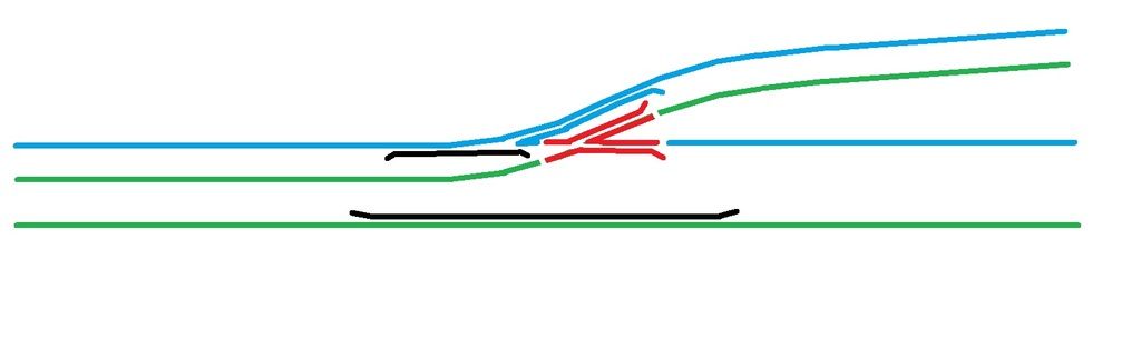
Blue and green are + or - depending. Red is crossing to be switched as either blue or green and black is unpowered.
“He who dares not offend cannot be honest.” Thomas Paine
https://www.sparkshotcustomcreations.com/
Mostly 3D Printed Loco kits etc.
SCC Price list (7/4/22)
https://www.sparkshotcustomcreations.co ... e77d42.pdf
https://www.sparkshotcustomcreations.com/
Mostly 3D Printed Loco kits etc.
SCC Price list (7/4/22)
https://www.sparkshotcustomcreations.co ... e77d42.pdf
-
jim s-w

- Posts: 2190
- Joined: Wed Jul 30, 2008 5:56 pm
Re: Changing frog polarity...
If it's DCC you can just use a frog juicer and it will sort itself out
-
grovenor-2685
- Forum Team
- Posts: 3923
- Joined: Sun Jun 29, 2008 8:02 pm
Re: Changing frog polarity...
If your loco pickups will bridge the crossing then you could just leave the red bit dead. This is one of few formations that occurs without any moving blades to link a switch with. To switch the crossing a basic 2 position switch is all you need, common connected to the red section and the other two contacts to the blue and green. As Jim says, for DCC a frog juicer would do it.
Regards
Regards
You do not have the required permissions to view the files attached to this post.
-
Knuckles
- Posts: 1262
- Joined: Fri Nov 18, 2011 9:15 pm
Re: Changing frog polarity...
The layout will be DCC eventually but I prefer to stick to conventional wiring for these things minus so many section breaks. I won't be using any DCC equipment for points and such like. I only wany DCC control for a few things not an all out control method.
The section definetly needs to be powered, can't have a dead crossing here, already tried it and nothing moves!
If the switch is just a simple 3 wire one with 2 positions is that a Single or Double pole Double Throw or is it simple a case of going Maplins and finding one that fits the description? I can go buy one then. Sorry for coming across thicker than a sleeper but electronics are not my area yet.
Thanks for your help.
Last edited by Knuckles on Sat Jul 30, 2016 4:19 pm, edited 1 time in total.
“He who dares not offend cannot be honest.” Thomas Paine
https://www.sparkshotcustomcreations.com/
Mostly 3D Printed Loco kits etc.
SCC Price list (7/4/22)
https://www.sparkshotcustomcreations.co ... e77d42.pdf
https://www.sparkshotcustomcreations.com/
Mostly 3D Printed Loco kits etc.
SCC Price list (7/4/22)
https://www.sparkshotcustomcreations.co ... e77d42.pdf
-
grovenor-2685
- Forum Team
- Posts: 3923
- Joined: Sun Jun 29, 2008 8:02 pm
Re: Changing frog polarity...
Single Pole double throw is all you need, but Double pole double throw gives you a spare contact and may be easiwer to get or at the same price.
Regards
Regards
-
Knuckles
- Posts: 1262
- Joined: Fri Nov 18, 2011 9:15 pm
Re: Changing frog polarity...
Ok many thanks.
Once it is all done I can do a post on it all.
Edit: Just seen you edit the above with a diagram. Once again, Keith you're a star, thank your for your effort.
This is how I was trying describe what I thought was the answer but was not sure. Off to our local Maplins tomorrow morning I think.
Once it is all done I can do a post on it all.
Edit: Just seen you edit the above with a diagram. Once again, Keith you're a star, thank your for your effort.
This is how I was trying describe what I thought was the answer but was not sure. Off to our local Maplins tomorrow morning I think.
“He who dares not offend cannot be honest.” Thomas Paine
https://www.sparkshotcustomcreations.com/
Mostly 3D Printed Loco kits etc.
SCC Price list (7/4/22)
https://www.sparkshotcustomcreations.co ... e77d42.pdf
https://www.sparkshotcustomcreations.com/
Mostly 3D Printed Loco kits etc.
SCC Price list (7/4/22)
https://www.sparkshotcustomcreations.co ... e77d42.pdf
-
Knuckles
- Posts: 1262
- Joined: Fri Nov 18, 2011 9:15 pm
Re: Changing frog polarity...
Switch purchased, installed and working correctly!
Many thanks again.
blog and vlog entry coming up...at some point.
EDIT: https://www.youtube.com/watch?v=qhcaCXzishw
Blog update on it in layout thread, '1st P4 layout.'
Many thanks again.
blog and vlog entry coming up...at some point.
EDIT: https://www.youtube.com/watch?v=qhcaCXzishw
Blog update on it in layout thread, '1st P4 layout.'
Last edited by Knuckles on Fri Jan 13, 2017 5:06 pm, edited 1 time in total.
“He who dares not offend cannot be honest.” Thomas Paine
https://www.sparkshotcustomcreations.com/
Mostly 3D Printed Loco kits etc.
SCC Price list (7/4/22)
https://www.sparkshotcustomcreations.co ... e77d42.pdf
https://www.sparkshotcustomcreations.com/
Mostly 3D Printed Loco kits etc.
SCC Price list (7/4/22)
https://www.sparkshotcustomcreations.co ... e77d42.pdf
-
Knuckles
- Posts: 1262
- Joined: Fri Nov 18, 2011 9:15 pm
Re: Changing frog polarity...
Well, I wasn't planning on posting any of my N gauge VLOGS as I don't see it being appropriate for S4 (I model in several scales) but seeing as I have just installed my first SEEP point motor and got it working I thought I'd share my trial with anyone who may be interested or maybe even need a mini visual idea on it. It's a multi scale/gauge issue anyway.
https://www.youtube.com/watch?v=u9Od83szOFM
https://www.youtube.com/watch?v=u9Od83szOFM
“He who dares not offend cannot be honest.” Thomas Paine
https://www.sparkshotcustomcreations.com/
Mostly 3D Printed Loco kits etc.
SCC Price list (7/4/22)
https://www.sparkshotcustomcreations.co ... e77d42.pdf
https://www.sparkshotcustomcreations.com/
Mostly 3D Printed Loco kits etc.
SCC Price list (7/4/22)
https://www.sparkshotcustomcreations.co ... e77d42.pdf
Who is online
Users browsing this forum: ClaudeBot and 0 guests