Some rather lovely custom etches arrived recently, produced by Rumney Models from design sketches provided by me. These will provide parts for the chassis and some body detailing to supplement a set of profile milled parts from Jeremy Suter and some dummy valvegear parts from Dave Bradwell from his J39 kit.
Hopefully, all the parts will gel together to produce a fair representation of C13, No. 67421, as running in the mid to late 1950s - superheated, mechanical lubricator, patch plates on the tanks and bunker and vacuum push-pull fitted.
The loco will haul two push-pull converted ex-GCR coaches I purchased some time ago from Larry Goddard and converted to P4.
Jusin's lovely etches:
Dave.
New project - ex-LNER C13, 67421
-
Dave Holt
- Posts: 555
- Joined: Thu May 28, 2009 9:44 pm
New project - ex-LNER C13, 67421
You do not have the required permissions to view the files attached to this post.
-
johndarch

- Posts: 162
- Joined: Tue Jan 29, 2019 11:24 am
Re: New project - ex-LNER C13, 67421
Looking forward to seeing the progress reports on the build Dave.
-
Alan Woodard
- Posts: 67
- Joined: Tue Sep 26, 2017 3:15 pm
Re: New project - ex-LNER C13, 67421
Hi Dave.
Will the etches be available to buy ?
Alan.
Will the etches be available to buy ?
Alan.
-
Dave Holt
- Posts: 555
- Joined: Thu May 28, 2009 9:44 pm
Re: New project - ex-LNER C13, 67421
Alan.
That would be up to Justin. However, I would point out that the etches are not a loco kit, being simply supplementary to parts from other sources, particularly the body. Also, there are no instructions and now even I'm a bit unsure how some of the parts are meant to go together!
Dave.
That would be up to Justin. However, I would point out that the etches are not a loco kit, being simply supplementary to parts from other sources, particularly the body. Also, there are no instructions and now even I'm a bit unsure how some of the parts are meant to go together!
Dave.
-
Alan Woodard
- Posts: 67
- Joined: Tue Sep 26, 2017 3:15 pm
Re: New project - ex-LNER C13, 67421
Ah, Ok. Just thought I'd ask.
Cheers Dave.
Al.
Cheers Dave.
Al.
-
iak

- Posts: 570
- Joined: Thu Nov 05, 2009 10:28 am
Re: New project - ex-LNER C13, 67421
Wibbling furiously... 
Unthinking respect for authority is the greatest
enemy of truth....
Albert Einstein
Perfection is impossible.
But I may choose to serve perfection....
Robert Fripp
https://www.facebook.com/groups/PadgateWorks/
enemy of truth....
Albert Einstein
Perfection is impossible.
But I may choose to serve perfection....
Robert Fripp
https://www.facebook.com/groups/PadgateWorks/
-
ralphrobertson
- Posts: 284
- Joined: Wed Nov 27, 2013 3:57 pm
Re: New project - ex-LNER C13, 67421
Hi Dave,
Presume you have the Reddy drawings for this, if you don't let me know and I will copy them for you. A Nucast C13 was my second P4 loco some 50 years ago together with tank patches. I had photos of 67436 on a special on the CLC at Winsford on the salt branch and I used that as a prototype. It used a cast whitemetal 40:1 gearbox made by Model Wagon Company if I remember, this predated the later lost wax ones and it was a long time before etched versions and it shows how long ago it was. I do still have the model - somewhere!
Will follow this with interest, I am sure it will turn out to be a superb model. I will be very interested to see what you do about the cab roof though. Somewhere I have a lost wax one which Andy Gibb had made when he modelled Whetstone all those years ago but last time I wanted to find it I had no idea where I had put it away!
Ralph
-
Dave Holt
- Posts: 555
- Joined: Thu May 28, 2009 9:44 pm
Re: New project - ex-LNER C13, 67421
Ralph,
This project started with a ready built Nu-cast model, acquired by a friend from e-bay. It had been assembled using adhesive and I managed to reduce it, mostly, back to the component parts by soaking in a bath of cellulose thinners for an extended period. However, I was rather disappointed by the dimensional accuracy and general quality apart from the chimney and dome. Also, I managed to snap off a couple of the footsteps.
I then saw Jeremy Suter's C13 running on Knutsford and asked about its origins. He explained that he had made a set of profile milled parts to aid construction and kindly agreed to produce a further set for me. A very nice cab roof is included.
I had obtained a copy of the RM article and drawings (from RM) - are these the "Reddy" drawings you mention? If not I would appreciate a copy.
I had also bought the GA and Pipe & Rod drawings from the NRM. These prompted me to want to replicate the inside motion (non-working), hence my commissioning the etches from Justin at Rumney. Besides the chassis parts, various additional detailing parts for the body were included. There will also be a number of 3D printed items to follow. Jeremy also turned a lovely chimney, dome and snifting valve for me.
I have started work by cutting out and cleaning up the main frame and overlays (and some of the spacers - not shown). These need to be fixed together before joggling the frame plates, as per the prototype.
Here are the main, fold-up inner frames and the two outer overlays. One has been modified at the upper front to better suite the body interface. The other shows the snap line created using an Olfa cutter.
Here one overlay has been (temporarily) attached to the inner frames using two 14 BA set screws and nuts. I later separated them to clear out the various slots in the inner frames where the tabs on the spacers locate.
Dave.
You do not have the required permissions to view the files attached to this post.
-
ralphrobertson
- Posts: 284
- Joined: Wed Nov 27, 2013 3:57 pm
Re: New project - ex-LNER C13, 67421
Hi Dave,
The Reddy articles are indeed those from Railway Modeller. There were 2 sets of drawings though, the first was June 1967 and was for 'Robinson 4-4-2T's of the GC' and the other was November 1968 which was for 'LNER Push-pull' which included both the converted C13 and coaches.
If you don't have both let me know and I will copy them for you.
Ralph
-
Dave Holt
- Posts: 555
- Joined: Thu May 28, 2009 9:44 pm
Re: New project - ex-LNER C13, 67421
Thanks, Ralph. I've got the LNER push-pull version, at least, and that's the relevant one for my late 1950s period.
Dave.
Dave.
-
Dave Holt
- Posts: 555
- Joined: Thu May 28, 2009 9:44 pm
Re: New project - ex-LNER C13, 67421
The main frame stretchers have been prepared, including the motion plate with its brackets either side, and loosely placed in position in the slots in the inner frames. In practice, these will be sprung into place in the folded up and joggled frame unit. I might try to keep the cylinder rear cover and motion plate, joined by the slidebars, as a separate loose insert, at least till the dummy inside valve gear has been assembled.
Dave.
Dave.
You do not have the required permissions to view the files attached to this post.
-
Dave Holt
- Posts: 555
- Joined: Thu May 28, 2009 9:44 pm
Re: New project - ex-LNER C13, 67421
The slide bars have been folded up and fixed into the slots in the cylinder rear cover. They proved to be rather delicate and tricky job to file off the etch cusp and fold and fit without destroying them.
Anyway, after a bit of tweaking and fettling, here they are temporarily fitted into the motion bracket and loosely slotted into the frames.
Wont be able to put off laminating and joggling the frames for much longer.
Dave.
Anyway, after a bit of tweaking and fettling, here they are temporarily fitted into the motion bracket and loosely slotted into the frames.
Wont be able to put off laminating and joggling the frames for much longer.
Dave.
You do not have the required permissions to view the files attached to this post.
-
Dave Holt
- Posts: 555
- Joined: Thu May 28, 2009 9:44 pm
Re: New project - ex-LNER C13, 67421
Further progress with the C13 chassis. Crazily, I did the trickiest bits between 1 and 2 am, this morning - after a meal out and a visit to the pub. Despite that, it seems to have gone quite well.
First, the frame overlays were attached to the fold-up inner. I used 179 degree solder, stating in the middle and slowly working outwards, soldering short lengths at top and bottom edges, to try and prevent any wrinkling of the thin overlays. The layers were held together using the two 14 BA screws, hair grips (as previously shown) and parallel jaw pliers held close to the stretch being soldered.
The result was this:
The laminated frames were joggled at the half-etched bend lines, initially using a couple of multi-layer jigs from the etch under the outer ends and the edge of my set square pressing down behind the inner fold line, generally as shown here, although this photo was taken after final folding of the chassis, as I neglected to take any photos at the time.
Unfortunately, perhaps due to the stiffness of the laminated frames and short moment arm for the bending operation, the resultant depth of joggle was insufficient and had to be adjusted by incremental further bending by hand, holding the parts of the frames either side of the joggle in parallel jaw pliers. The required amount of joggle was checked using the shank of a 1.1 mm drill bit against a straight edge, generally as shown here.
All the joggling was done with the frames in the flat, so to speak. Once the joggling was deemed satisfactory, the frame assembly was folded, by hand and in small increments at the four folds, until the frame plates were at right angles to the integral spacers. After adjustments to ensure squareness and freedom from twist, the folds were reinforced with solder, the front ends of the frames bent inwards and soldered.
Here are the folded up frames.
Trial loose fitting of some of the frame stays has revealed some design errors which will require some slight modifications to my original ideas. Hopefully nothing too drastic.
Dave.
You do not have the required permissions to view the files attached to this post.
-
Dave Holt
- Posts: 555
- Joined: Thu May 28, 2009 9:44 pm
Re: New project - ex-LNER C13, 67421
The footplate required some small modifications to enable it to fit to my chassis design. This involved extending the central hole at the front to accommodate the top of the frames sticking through and to allow for the joggled frame plates. Unfortunately, I misjudged the rear mounting hole in the chassis etch and it's roughly half a hole out. Not too hard to overcome when the time comes.
The rear spacers have been soldered in and the centre "Z" spacer loosely clipped into its slot. All still seems good.
Dave.
The rear spacers have been soldered in and the centre "Z" spacer loosely clipped into its slot. All still seems good.
Dave.
You do not have the required permissions to view the files attached to this post.
-
Dave Holt
- Posts: 555
- Joined: Thu May 28, 2009 9:44 pm
Re: New project - ex-LNER C13, 67421
I thought I aught to get on with some of the functional bits, so assembled the High Level horn guides and axle boxes. A slight modification was necessary to allow the guides to fit higher in the frame cut-outs than normal, to allow the bottom edge to be level with the bottom of the frames.
My Avonside Works chassis jig had already been set up using the coupling rods, as seen here.
With the etched hole over one jig post, the first horn guide/axle box was positioned,
then fixed to the frame plate. Note the centre pop marks on the underside of the axle box to identify its location. There's a similar marking on the horn guide, not visible in the photo).
Then the other side was attached.
The next operation will be to saw out the front axle fillers and use the jug to locate the front horn guides from the rears already fitted.
Dave.
You do not have the required permissions to view the files attached to this post.
-
Dave Holt
- Posts: 555
- Joined: Thu May 28, 2009 9:44 pm
Re: New project - ex-LNER C13, 67421
The front axle hornguides have been fitted using the chassis jig and locating off the rear axleboxes, already fitted. Further progress includes fitting the brake hanger pivots and the main compensating beams. These latter proved to be quite a struggle to get into position due to my poor planning and design but, with a bit of judicious bending and lots of wiggle, they are finally in place, as seen here.
Te final part added today was the ash pan, the rear end of which locates the fore end of the rear keepers. The front keepers locate in a slot at the bottom of the front "Z" frame spacer.
Dave.
Te final part added today was the ash pan, the rear end of which locates the fore end of the rear keepers. The front keepers locate in a slot at the bottom of the front "Z" frame spacer.
Dave.
You do not have the required permissions to view the files attached to this post.
-
Dave Holt
- Posts: 555
- Joined: Thu May 28, 2009 9:44 pm
Re: New project - ex-LNER C13, 67421
Ploughing on, the axle box keeps have been folded up and temporarily fixed in place with over-long 14 BA screws. The front ones were a bit of an exercise in nickel silver origami and very delicate until reinforced with solder at the folds. I have no idea about the origins of the cast brass coil springs. They were on some sprues with some nice leaf springs, which I must have acquired from somewhere.
The rear, leaf springs are not quite right, so I haven't laminated the layers and am just using them till a corrected version is produced.
Sorry about the photo quality, but they show the basic arrangements.
I have discovered a fundamental error in my original sketches for the compensating beam. The bottom edge of the bearing surface onto the tops of the axleboxes is 0.473 mm too low relative to the pivot axis. It doesn't seem practical to take the beams out, now, so careful (and, no doubt, laborious) filing through the horn gaps would appear to be the only solution. Something I'm definitely not look forward to doing. Damn.
Dave.
You do not have the required permissions to view the files attached to this post.
-
Dave Holt
- Posts: 555
- Joined: Thu May 28, 2009 9:44 pm
Re: New project - ex-LNER C13, 67421
I've parked the compensating beam issue as being too difficult and moved on to something, hopefully, more straight forward - the dummy inside valve gear.
As previously mentioned, this is based around Dave Bradwell's J39 chassis with some parts replaced by etchings to my design to better represent the prototype. So far, I've done the eccentrics and inner crank webs, leaving the con rods still to do. I found it necessary to slightly shorten the eccentric rods, by cutting and splicing, to suit the spacing between the crank axle and the motion plate, which must be less on the C13 than the J39. The con rods will also need shortening.
Here the assembled valve gear is temporarily loose fitted into the frames.
That will be it till next week as I'm off to Scaleforum in High Wycombe tomorrow. I'll have the chassis with me if anyone is interested.
Dave.
You do not have the required permissions to view the files attached to this post.
-
Will L

- Posts: 2527
- Joined: Sun Jul 20, 2008 3:54 pm
Re: New project - ex-LNER C13, 67421
While your worrying about the compensation on the chassis, and given I'm interested in the dynamics of chassis suspension, I'd like to stick in my two penny worth.
Assuming your three point compensation is between the twin beams on the main drivers and the bogie pivot, the optimum place for the loco Center of Gravity (CofG) is on or just in front of the leading driving axle.
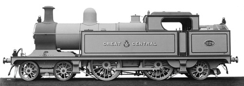
Image courtesy of the LNER encyclopaedia
Given the body shape this is not going to happen naturally. The natural CofG point is probably central between the driving wheels directly over the compensation pivot, but the further it gets from the optimum towards the natural the more likely it will routinely derail its bogie. Should the CofG actual fall on or behind the compensation pivot point there will be no weight on the bogie at all and the loco will try to sit back on the pony/radial truck. You can compensate for this by putting a spring over the truck but very careful adjustment is likely to be needed to get sufficient weight on the bogie to keep it honest and not to take too much weight off the drivers.
The truth is that going for the twin beams over the driving axle makes compensation a bit tricky. The classic 4-4-0 compensation solution with a fixed rear driving axle and a single compensation beam over the leading driver/bogies is a lot more stable and a lot more tolerant of where the CofG turns up. However I suspect you're to far down the road to go that way.
Knutsford had two 4-4-2s a C12 (CSBd) and a C13(Fully Compensated). The CSB chassis, just like the fully compensated one, was sensitive to where the CofG is. Just to show its possible,how I got the C12 running well is documented elsewhere.
Assuming your three point compensation is between the twin beams on the main drivers and the bogie pivot, the optimum place for the loco Center of Gravity (CofG) is on or just in front of the leading driving axle.
Image courtesy of the LNER encyclopaedia
Given the body shape this is not going to happen naturally. The natural CofG point is probably central between the driving wheels directly over the compensation pivot, but the further it gets from the optimum towards the natural the more likely it will routinely derail its bogie. Should the CofG actual fall on or behind the compensation pivot point there will be no weight on the bogie at all and the loco will try to sit back on the pony/radial truck. You can compensate for this by putting a spring over the truck but very careful adjustment is likely to be needed to get sufficient weight on the bogie to keep it honest and not to take too much weight off the drivers.
The truth is that going for the twin beams over the driving axle makes compensation a bit tricky. The classic 4-4-0 compensation solution with a fixed rear driving axle and a single compensation beam over the leading driver/bogies is a lot more stable and a lot more tolerant of where the CofG turns up. However I suspect you're to far down the road to go that way.
Knutsford had two 4-4-2s a C12 (CSBd) and a C13(Fully Compensated). The CSB chassis, just like the fully compensated one, was sensitive to where the CofG is. Just to show its possible,how I got the C12 running well is documented elsewhere.
-
davebradwell
- Posts: 1181
- Joined: Fri Jan 18, 2019 3:48 pm
Re: New project - ex-LNER C13, 67421
Your comments might be true enough, Will but a cure involving a single fixed driving axle must be the last resort in desperation. Dave will sort it out, somehow.
DaveB
DaveB
-
Will L
- Posts: 2527
- Joined: Sun Jul 20, 2008 3:54 pm
Re: New project - ex-LNER C13, 67421
davebradwell wrote:Your comments might be true enough, Will but a cure involving a single fixed driving axle must be the last resort in desperation. Dave will sort it out, somehow.
I wasn't trying to suggest Dave H did that, I don't like rigged driving axles any more than you do. In any event I thought the work already done on the inside motion would rule out the traditional approach. It was more a case of needing to be be aware of the issues he's going to face and ensure that things to come, like the design of the drive chain, leave him free to add enough weight in the right places. I'm sure its doable.
I suppose I shouldn't have confused things by adding the sentence on the classis 4-4-0 compensation system, but I just wanted to point out that, for those who might not want to tackle a fully suspended chassis, there is a relatively imple way out.
-
Dave Holt
- Posts: 555
- Joined: Thu May 28, 2009 9:44 pm
Re: New project - ex-LNER C13, 67421
Thanks for the comments, Will and Dave B. I already was fully aware of the CofG issue at the planning stage. As Will rightly surmises, the dummy inside valve gear rather precludes a single beam between bogie and front coupled axle and, as stated by both, I also do not like fixed axles. Early on in my modelling, I had bad experience with such arrangements, including the lifting of the inside wheel of the fixed axle on curves taken at speed.Also, of course, a fixed axle causes the loco to lurch over any vertical misalignment in the track. Incidentally, my origin design was to use individual guitar wire springs on the coupled and rear truck axles and springy beams on the bogie. I even did all the calcs for support spans, etc., but somewhere along the line I reverted to type and plumped for my usual compensation. In the final version, the rear truck remains sprung, but using my hair-pin wire spring developed for the Ivatt and BR Standard tanks.
On this model, the motor will be vertically mounted under the firebox so, as a start the tanks and whole of the boiler barrel/smokebox will be packed with lead. There's also room for a bit extra inside the saddle and even between the front end of the frames. Time will tell if this proves adequate.
Dave.
-
Chris Pendlenton
- Posts: 57
- Joined: Wed Dec 30, 2009 7:14 pm
Re: New project - ex-LNER C13, 67421
My preferred solution to Dave’s dilemma would be to look at what Mr Robinson did and install individual axlebox suspension to all wheels, spreading the load to driver and carrying axles in approximate proportions of 2 to 1, ie “L” to each driving axle and half “L” to each carrying axle (or “L” to a bogie) To help find trim and optimal adhesion on a 4 4 2 it is best the driving axleboxes are adjustable. You can avoid having to fit extra spring foundation points and keep the springing very discrete to each axlebox by using home wound phosphor bronze wire coils trapped between axlebox top and an upside down 10ba cheesehead screw adjuster with a turned “land“ on the head, let into a tapped hole in the top of the hornguides. Springs made as per my Deltic article. I have many engines thus fitted, all well behaved. Accurate weight distribution can be found from prototype Weight Diagrams and was described in MRJ 6 when some of you (but not Dave) were in short trousers.
Chris
Chris
-
petermeyer
- Posts: 313
- Joined: Tue Oct 01, 2013 10:06 am
Re: New project - ex-LNER C13, 67421
Dave Holt wrote:Early on in my modelling, I had bad experience with such arrangements, including the lifting of the inside wheel of the fixed axle on curves taken at speed.
Thanks for this insight. I've noticed the same thing on my 4-4-0 LNWR Precursor now that my layout has curves and I did wonder it the fixed axle was the problem! Seems like a rebuild is required.
-
Dave Holt
- Posts: 555
- Joined: Thu May 28, 2009 9:44 pm
Re: New project - ex-LNER C13, 67421
Peter.
The problem I mentioned was down to a combination of factors, most importantly, the position of the CofG relative to the compensation pivot positions, not just the fixed rear axle.
Beam compensation basically provides three fixed points of support, thus ensuring all wheels stay in contact with the rail. In plan view, there is a triangle of support points with a fixed rear axle or the pivots of a twin beam arrangement forming the base of the triangle and the pivot of the single beam or rocking point being the apex. When taking curves the centrifugal force moves the effective point of the CofG laterally and,if the CofG is too near the apex and it crosses the side of the triangle, the loco becomes unstable - like a child's tricycle toppling over if cornering too fast. This was the main issue with my early models, which had the fixed rear axle and a single beam between the front and middle coupled axles (with a non-load bearing bogie just along for the ride). The outside cylinders, cast W/M boiler and lead ballast, etc., all helped move the CofG too far forward. Hence the problem.
Ideally, the CofG should coincide with the centroid of the triangle, one third up from the base line. On a 4-6-0, with twin rear beams and the apex support at the bogie pivot, this centroid position also results in almost the ideal weight distribution, closely matching that of typical prototypes, with roughly equal load on the three coupled axles (ignoring the axle hung weight from the motor and drive train) and the same on the bogie centre.
I find this arrangement gives excellent stability, traction and minimum lurching over track irregularities.
As discussed above, it's not so easy to arrange this ideal arrangement on a 4-4-2 tank or, perhaps, even a 4-4-0.
I suggest that your problem with you Precursor can be overcome by adding weight to move the CofG backwards or arranging for some of the tender weight to bear on the back of the loco.
Dave.
Who is online
Users browsing this forum: ClaudeBot and 0 guests