Furness J1 Class - Complete!

User avatar
Knuckles
Posts: 1262
Joined: Fri Nov 18, 2011 9:15 pm

Furness J1 Class - Complete!

Postby Knuckles » Wed Sep 28, 2016 10:11 am

Unlike the Furness K2 thread where I basically video logged the build of a freelance variant and then showed it you, in this one I will give standard blog style updates so you can see the progress.

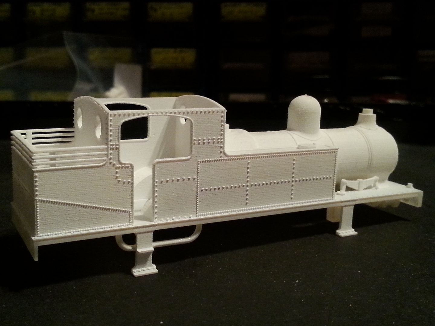
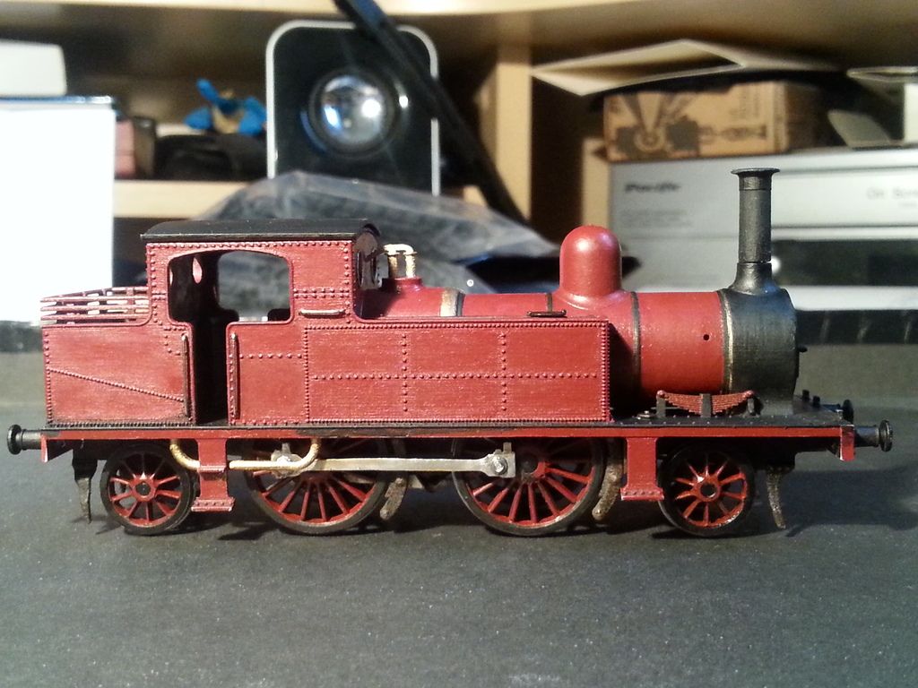
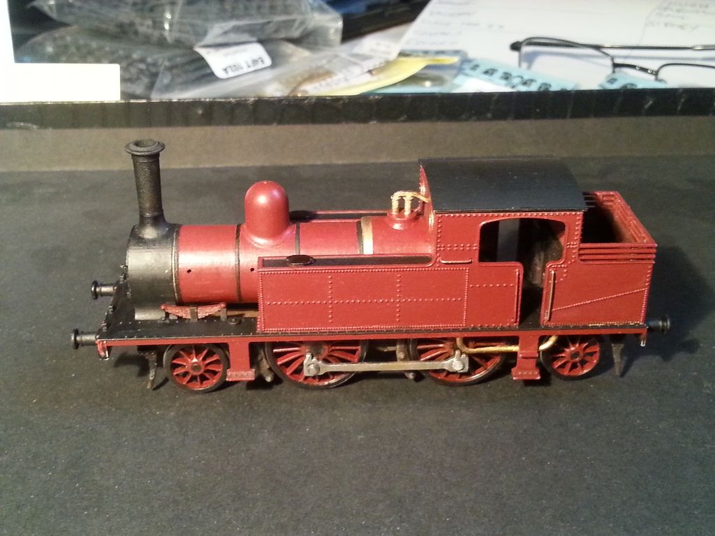
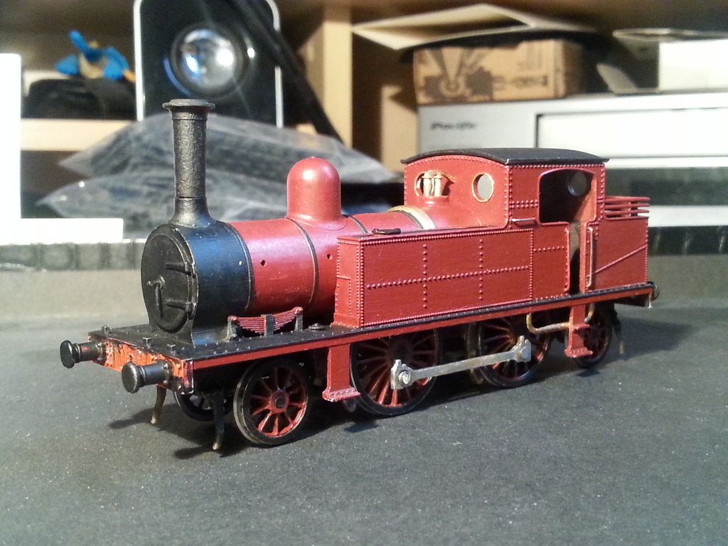
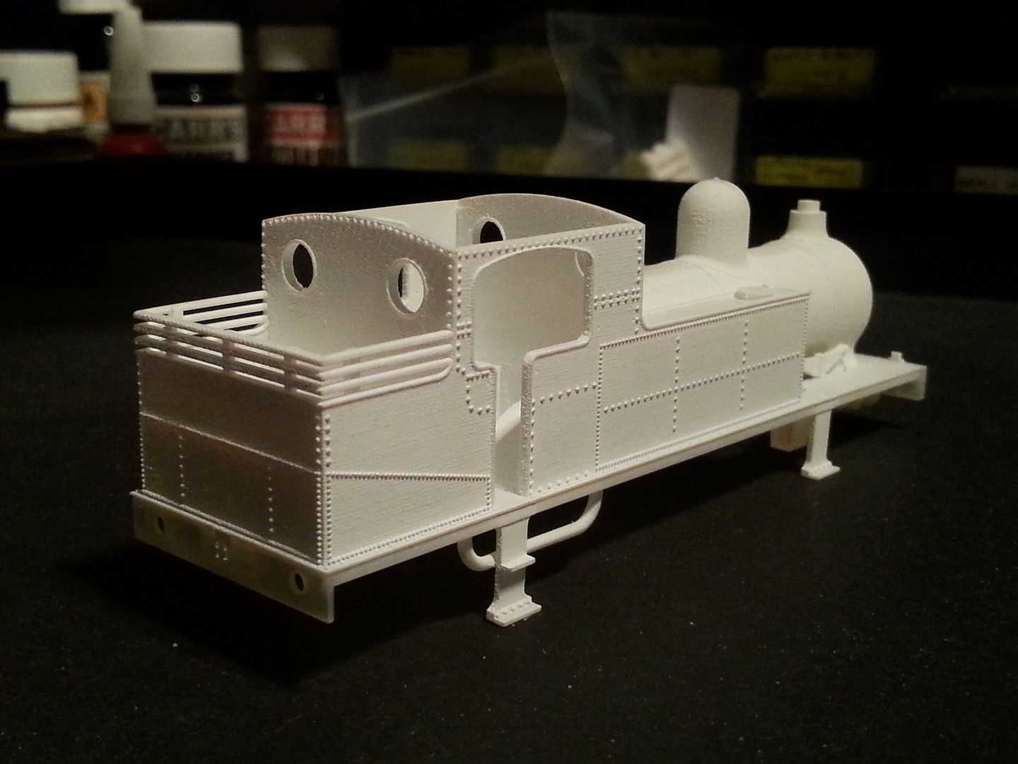
Ok then, time for something tangible. It's been over 6 months of riveting 'meshin,' for the J1, very much indeed because of all those damn rivets. In the research it seemed quite clearly that there were at least 3 different rivet patterns for the J1 and so these took most of the time, positioning the correct amount in the spaces provided and sizing them was a swine cake, then I decided to round them all off as they should be and it caused all those lagging issues previously explained. So as a reminder, the body comes with 1 small chimney shank that slots into the base, the buffers are sprued underneath and the smokebox is sprued roughly in place protruding a little. Cab roof is included and loose so non sprued. For the backhead and other chimneys due to the data issues you'll have to get the separate pack unfortunately. I did want them all in the same file but what can you do?


Anyway, enough waffle, here is a not so cheap FXD print on the desk after its white spirit dunk...


Bum view
Image


Almost bum view

Image


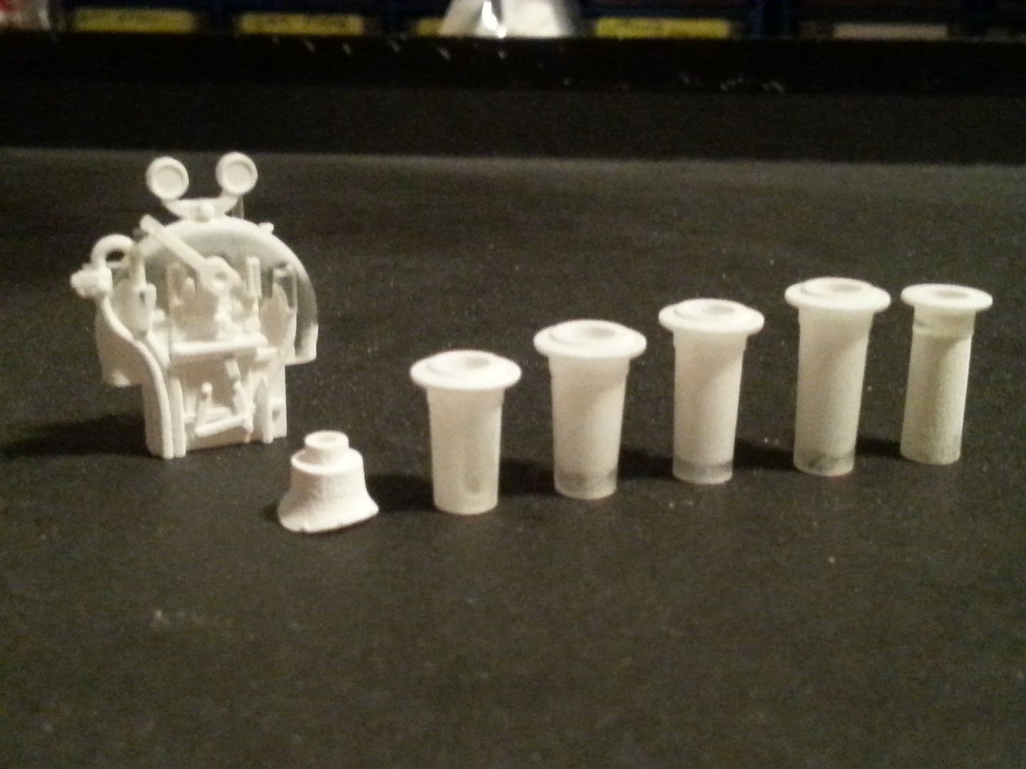
Chimneys and backhead (Backhead based on the K2 and tweaked slightly. Info lacking so if anything significant comes up it can be changed.)
Image

The optional base is so you can use them on a different engine if you want to. Good to at least give the option. Rather than the usual method of having loads of full chimneys to interchange having the shanks interchangeable instead allows you to change the engine or period to a degree at a whim. The chimney base has a slight step as it should before the main shank so it provides a perfect join point.


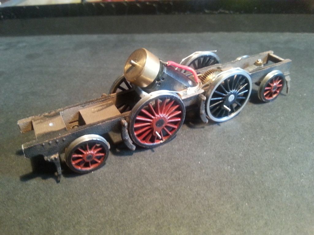
WSF P4 Chassis clipped into place. Fixed axle.
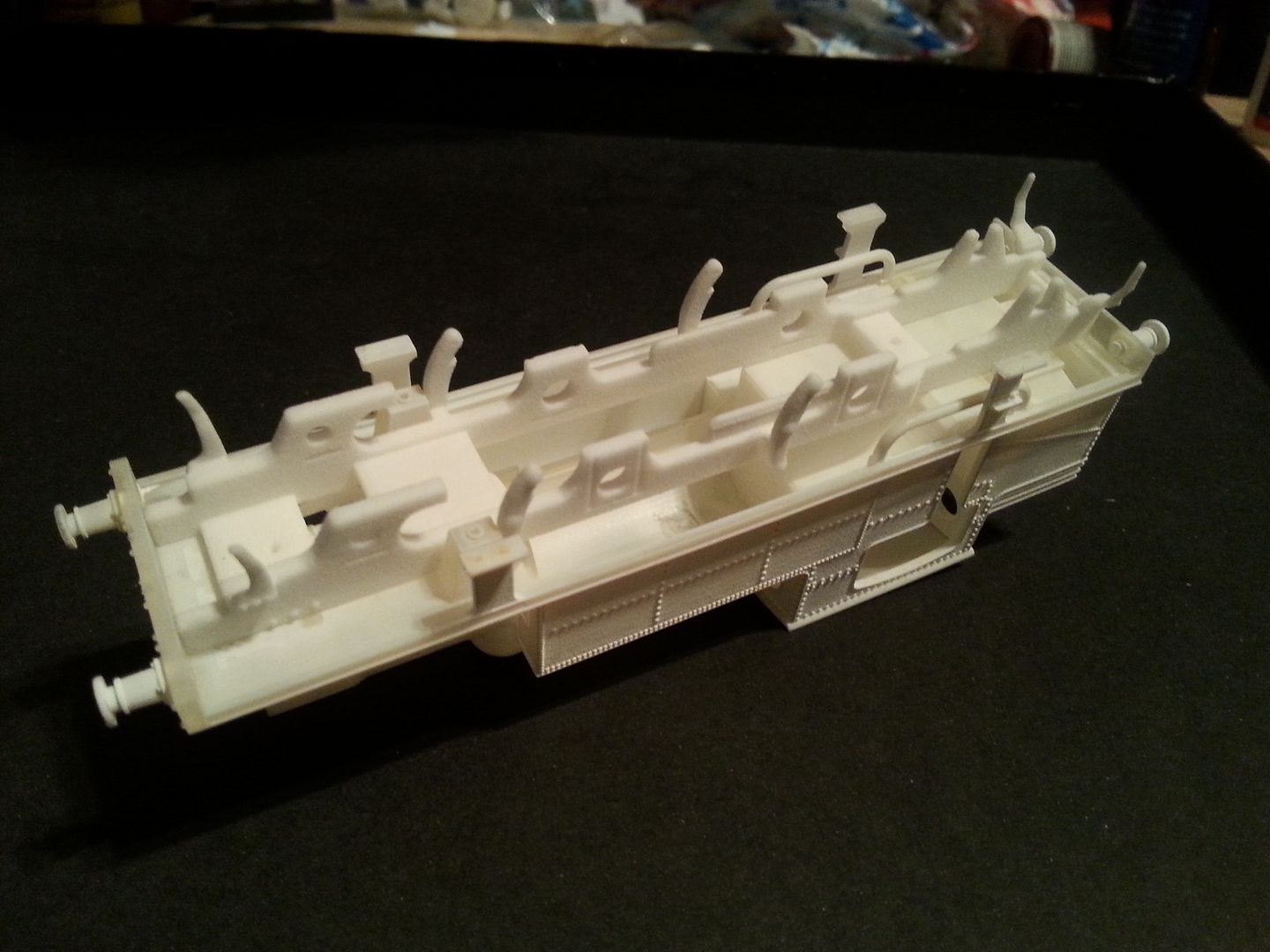
Image


Here we see the body with the small chimney plonked in position along with the roof for show.
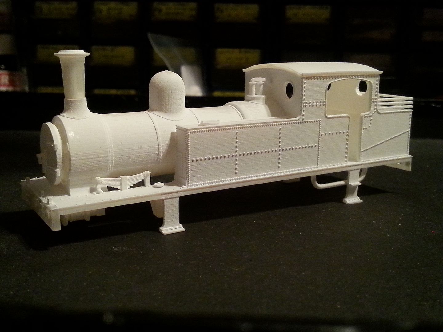
Image


And here we see the ancient looking 'Chocker' chimney on display instead, the smokebox door has been de-sprued and pushed home and the buffers likewise. The J1 also ran with several buffer types but the kit only has these more ornate ones. Others can be made if there is demand though.
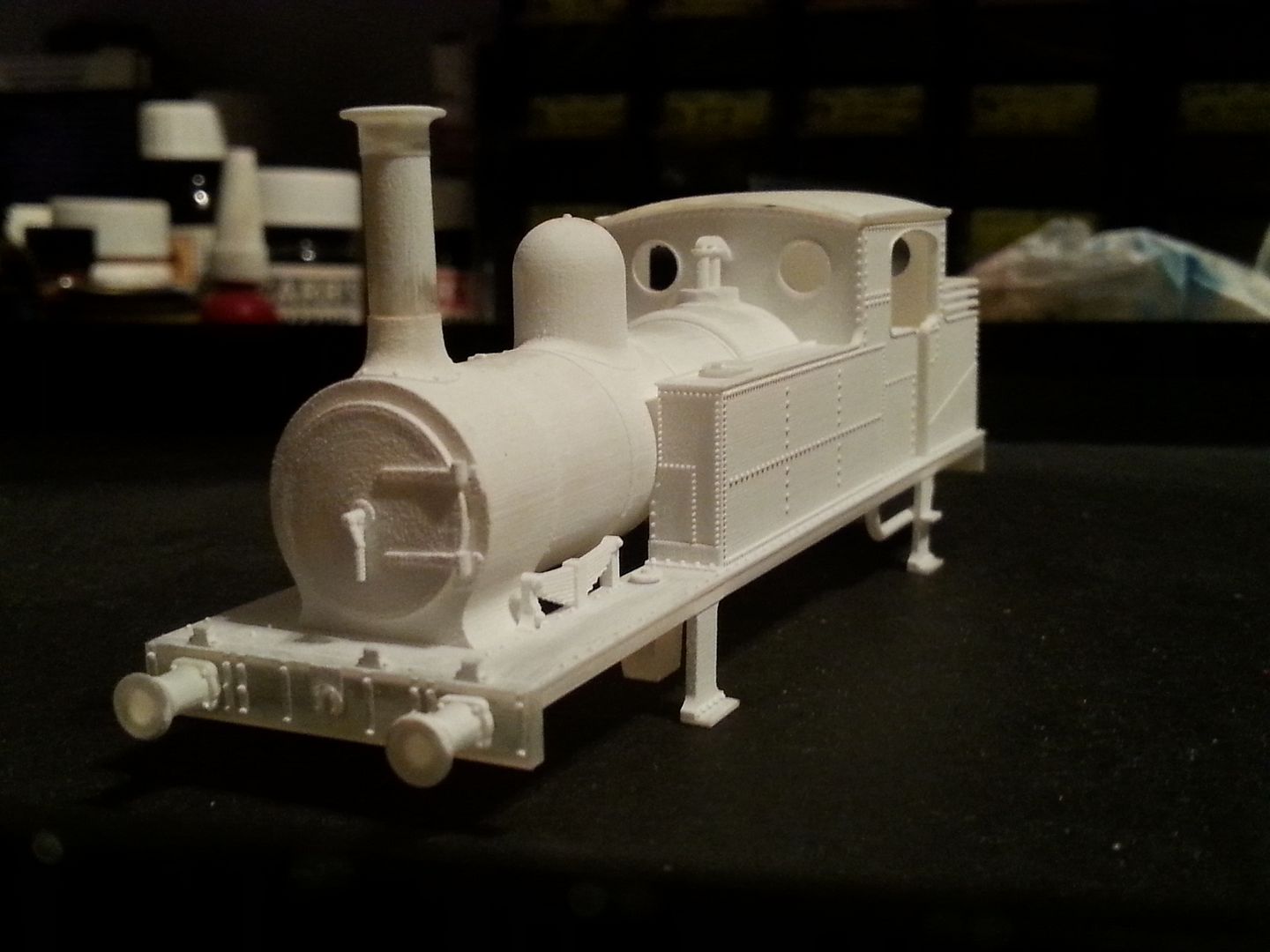
Image


And for now at least there you have it.


More waffle...


So as you can see the surface detail still needs a little clean up but it is so far better than the FUD prints that I have had...which are better than the WSF prints. Fibre glass brush and chiseling action carefully in between the nice rivets is the order of the day. I paid extra to reduce the amount of clean up required due to the rivets so thankfully it is smoothing down a lot easier. Whatever material you get from Shapeways they will (so far to my knowledge) require a certain amount of preparation work before painting, but either way it is about 30 times quicker than building up an etched kit! Not dissing etched kits BTW, very much a fan of them.


What I am going to do is build the P4 Chassis as a fixed axle, probably find out my mini layout doesn't like it (1: its P4, 2: I'm not the most experienced at building P&C) and then probably buy another chassis and try modifying it for compensation or springing. I have to date built a few etched kits and a few of these fixed axle SCC chassis but only one was done against the instructions when I tweaked a SE Finecast E2 chassis for P4 and Alan Gibson springing - which worked out pretty good.


Many (especially older) etched kits are designed as a fixed axle and the builder then has to modify them for compensating and springing. So far all the SCC chassis are of the same fixed axle format so there is no difference here. When I get around to modding one it will be as much of an experiment to me as it may be to some of you.


In the future I plan to incrementally bring in etched chassis for everything also to account for the traditional ways and then hopefully people can choose what they would like. A) The usual etched ways good for modifications, B) Easy peasy 3D printed ways less good for modifications. We can't please everyone in this life but we can try!


So with that I'll now go away.


Please drop some comments good or bad, until next time...


EDIT: Just noticed I forgot to add the leaf springs, what a numpty! Will edit the uploads soon.
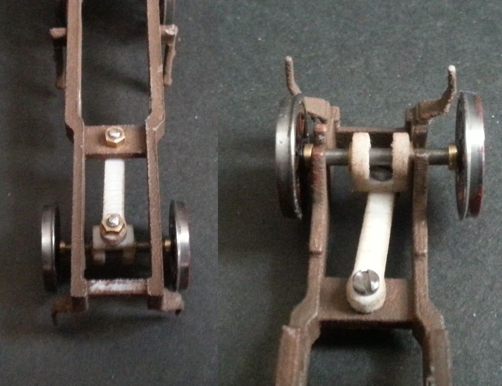
Last edited by Knuckles on Sat Dec 31, 2016 5:38 pm, edited 6 times in total.
“He who dares not offend cannot be honest.” Thomas Paine

https://www.sparkshotcustomcreations.com/
Mostly 3D Printed Loco kits etc.

SCC Price list (7/4/22)
https://www.sparkshotcustomcreations.co ... e77d42.pdf

David Knight
Posts: 819
Joined: Sun Jul 20, 2008 6:02 pm

Re: Furness J1 Class

Postby David Knight » Wed Sep 28, 2016 1:36 pm

Gavin,

Are there dimples to locate the hand rail knobs or is that something we have to figure out ourselves?

Cheers,

David

User avatar
Knuckles
Posts: 1262
Joined: Fri Nov 18, 2011 9:15 pm

Re: Furness J1 Class

Postby Knuckles » Wed Sep 28, 2016 7:34 pm

There are dimples, just very fine. About 0.4mm diameter.

The smokebox handrail pillars will need to be plotted though as it seems the prototype had differing combinations and I didn't want to poke holes where they might not be depending which version one may want.
“He who dares not offend cannot be honest.” Thomas Paine

https://www.sparkshotcustomcreations.com/
Mostly 3D Printed Loco kits etc.

SCC Price list (7/4/22)
https://www.sparkshotcustomcreations.co ... e77d42.pdf

User avatar
Knuckles
Posts: 1262
Joined: Fri Nov 18, 2011 9:15 pm

Re: Furness J1 Class - 90% Complete!

Postby Knuckles » Tue Oct 11, 2016 2:00 pm

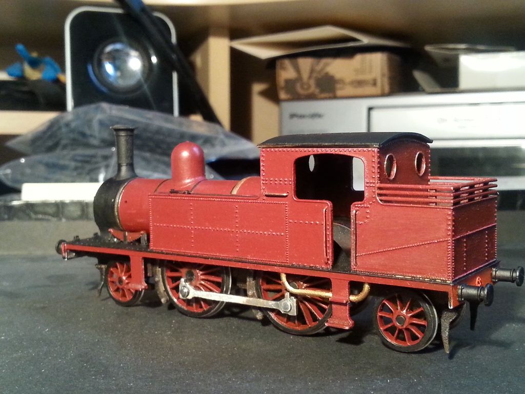
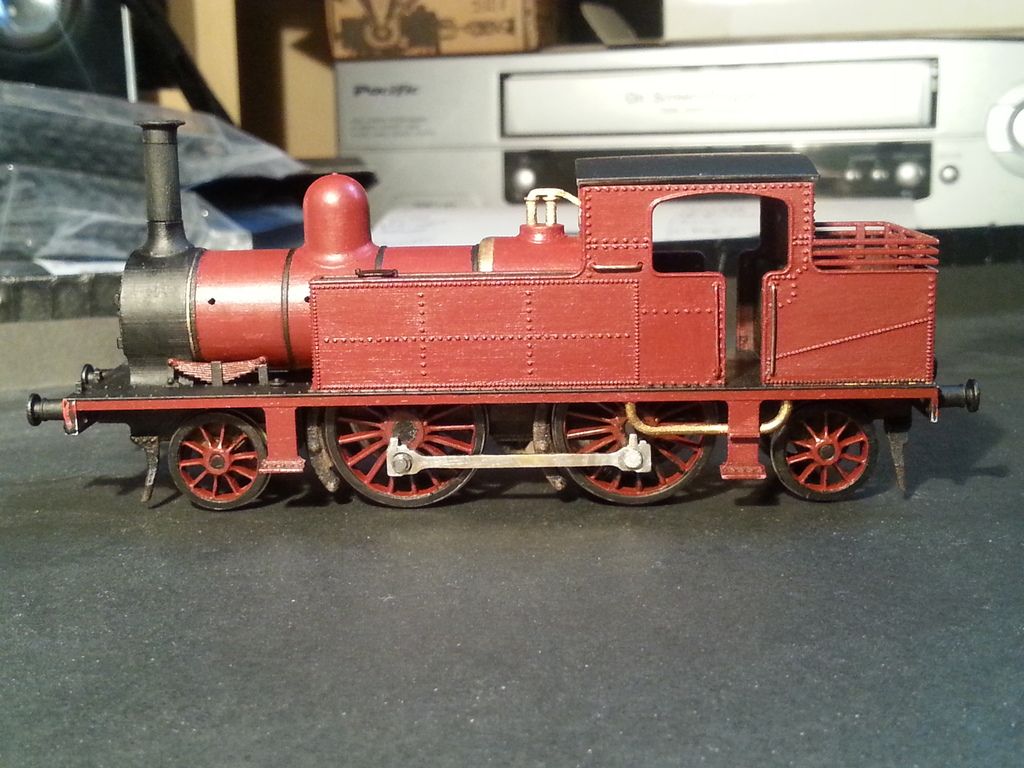
Major update time for the Furness J1 loco build, probably 85-90% done.

I will be updating and adding features to the chassis' very soon. The clearances are fine, very happy with how things have turned out. I however need to add leaf springs as I forgot and the cosmetic cylinder covers have been started seeing as they are very visual.

The front leading wheels have some downwards filing in the holes to allow the bearing to drop downwards a wee if needed, seems to be working well. I need to add pick ups on these wheels too but other than that it is running on the P4 layout without falling off so happy days init!

I made a mistake with the coupling rods as I reamed them out too much so to cure this the holes were reamed out even more and a washer soldered in place - the type Markits sell as crank pin retaining nuts. This was then opened out more carefully and voila, nice running.

The double joined radial truck can be built fixed if you want simply by gumming it up or using the other fixed arm provided to give Pony style swing instead. These are designed to be used with 10BA nuts and bolts as seen in the pics. The wheel insides have some 2mm bore 1mm thick washers in place to allow free rotation when 'touching' the frames.

Image

Image

The loco still needs a lot of work, more paint touch ups and a few details still need adding. The gear had to have a space in the cab floor cut but if using a different set up this may not be needed. I'm using as LRM 50:1 motor mount with a 1020 Mashima motor and a 12x6mm flywheel. After adding the backhead, controls and crew I doubt it'll even be noticeable, especially with the roof on. I had to thin the crank pin retainers and also the downward pipes for clearance, also had to bend them out a smidge but all good. In 00 you won't have to worry but this is a P4 example.

Paint needs some varnish once finished and I need to add transfers. I have the FR lettering but I cannot find proper FR lining and it seems the only way to do it properly is to make my own transfers...somehow. For now I guess I'll just have to line the tanks black like I have been doing with previous FR engines, maybe then I can go over it once I have proper black with thin vermilion(red) lines either side. LNWR and BR have lining like this but only on the straight sections rather than tank corners, also no idea if the red will be too thick or not. Ideas? Need etched plates too.

Ok, so, needs some more hand rails, smokebox dart repair, pipage from brass rod, sand and brake pipes, whistle and other bits no bobs to complete. Getting very close though! Chimney shanks need a bit of smoothing too as they had none and I just painted them, could do with a wee rub. I'm taking livery details from the Pochin models hence the odd wheel colouring. Pretty catching me thinks.

What follows is some shots of the engine in I estimate 85-90%, first is shown the small chimney, then the inwards to top tapering Chocker and then the larger chimney. Not all are shown here though. See what you think and please drop some comments if it interests you.

Image

Image

Image


Image

Image

If you like it, don't like it or have suggestions/questions please let me know. :)
Like buttons don't do much for communication. :/
“He who dares not offend cannot be honest.” Thomas Paine

https://www.sparkshotcustomcreations.com/
Mostly 3D Printed Loco kits etc.

SCC Price list (7/4/22)
https://www.sparkshotcustomcreations.co ... e77d42.pdf

User avatar
jon price
Posts: 641
Joined: Mon Jun 07, 2010 2:34 pm

Re: Furness J1 Class - 90% Complete!

Postby jon price » Tue Oct 11, 2016 3:55 pm

Very nice! You say this is expensive in FXD, and it is £120, but a kit would be the best part of £100, and would need making (involving time and skill), so maybe not so expensive for the time-poor. How similar is this to the GCR 2-4-2T do you know?
Connah's Quay Workshop threads: viewforum.php?f=125

User avatar
Knuckles
Posts: 1262
Joined: Fri Nov 18, 2011 9:15 pm

Re: Furness J1 Class - 90% Complete!

Postby Knuckles » Tue Oct 11, 2016 4:03 pm

jon price wrote:Very nice! You say this is expensive in FXD, and it is £120, but a kit would be the best part of £100, and would need making (involving time and skill), so maybe not so expensive for the time-poor. How similar is this to the GCR 2-4-2T do you know?


When looked at that way very true, 3DP saves a LOT of build time and instead of spending ages building you just spend a bit of time cleaning up and almost everything else is already done for you. You'd still have to buy a chassis (or make one), some rods, wheels, motor, gears etc etc like a normal kit though so it adds up.

Brexit really isn't helping much either. :/

Very much want a decent printer so I can at some point hopefully offer things at a better price.

Checked the loco you mentioned, at a glance it looks similar but I'd say it is longer, the boiler looks to be pitched higher, cylinders are higher and it has a belpair firebox so quite a lot of differences when scrutinized. Hope this helps. :)
“He who dares not offend cannot be honest.” Thomas Paine

https://www.sparkshotcustomcreations.com/
Mostly 3D Printed Loco kits etc.

SCC Price list (7/4/22)
https://www.sparkshotcustomcreations.co ... e77d42.pdf

User avatar
Penrhos1920
Posts: 231
Joined: Wed Jul 23, 2008 6:00 pm

Re: Furness J1 Class - 90% Complete!

Postby Penrhos1920 » Tue Oct 11, 2016 8:53 pm

Knuckles wrote:When looked at that way very true, 3DP saves a LOT of build time and instead of spending ages building you just spend a bit of time cleaning up and almost everything else is already done for you


How may hours gently scraping and rubbing have done on this nice little loco? It looks so much better in FXD - one of the best I've seen to date.

User avatar
Mike Garwood
Posts: 618
Joined: Sun Aug 03, 2008 4:51 pm

Re: Furness J1 Class - 90% Complete!

Postby Mike Garwood » Tue Oct 11, 2016 9:03 pm

Gavin

Looks like you've come a long way from your early efforts, have you found a way to spring any of your locos or is it still under development?
Excellent work.

Mike

User avatar
Knuckles
Posts: 1262
Joined: Fri Nov 18, 2011 9:15 pm

Re: Furness J1 Class - 90% Complete!

Postby Knuckles » Wed Oct 12, 2016 4:28 am

Thanks guys.

For smoothing probably when you add the time together an hour or two tops. If it was FUD or WSF it would be more.

Smoothing this one required the blunt end of a scalpel blade gently nocking off the slight layering between the tanks, gently rubbing with a fibre glass brush and the usual blast of primer followed by abraisive paper rubbing.

All materials require some prep work but I was pleasantly surprised that this required less than previous models.

Although I like to use air brush this has been brush painted as until I get a new mask I'm leaving the ol' Badger alone for a bit. Maybe with airbrush it would be better. It has since had some touch ups and its first Citadel Purity Seal satin varnish applied. Once I have figured what I am doing with the lining I think I'll risk it and try for a propper satin or a light gloss to the red paint for a change. So far all my Satin engines look to me more like Matt.


Springing is still in the pipeline, got some cunning planns but have the issue of choice followed by not being able to do everything at once so currently plan is go finish off this J1 (maybe 2) then finish the CAD on the E1 followed by the build, I then have some smaller projects lined up but in that time I may look inyo it more then.

I want to venture into etching so we can have the traditional chassis set ups we all like as an option too.

I need 12 hands though!
“He who dares not offend cannot be honest.” Thomas Paine

https://www.sparkshotcustomcreations.com/
Mostly 3D Printed Loco kits etc.

SCC Price list (7/4/22)
https://www.sparkshotcustomcreations.co ... e77d42.pdf

User avatar
jim s-w
Posts: 2189
Joined: Wed Jul 30, 2008 5:56 pm

Re: Furness J1 Class - 90% Complete!

Postby jim s-w » Wed Oct 12, 2016 10:26 am

Hi knuckles

It's looking good but I'm not sure it's good enough. It still looks too grainy too me if I'm honest. The footplate looks fine but the boiler and tank sides need more work. Also the thick edges round the doors and windows look too chunky. I don't like the buffers at all, they look like the ones Lima fitted to thier 08 30 years ago.

I wonder of you are trying to do too much with one material? As is filler primer sanded back should sort the boiler out but I really think etched overlays for the tanks and cabs would be the way to go. Also for the price, doing one spot on master this way and getting someone like CMA to copy 50 of them might turn out cheaper and better quality. I know you are trying to take the KISS approach for the end user but even if you went for the etched sides option as part of the kit, gluing them on has to be easier than trying to tidy up the sides without destroying the details.

Keep plugging away, you are getting there :thumb

HTH

Jim
Jim Smith-Wright

http://www.p4newstreet.com

Over thinking often leads to under doing!

User avatar
Knuckles
Posts: 1262
Joined: Fri Nov 18, 2011 9:15 pm

Re: Furness J1 Class - 90% Complete!

Postby Knuckles » Wed Oct 12, 2016 1:15 pm

jim s-w wrote:Hi knuckles

It's looking good but I'm not sure it's good enough. It still looks too grainy too me if I'm honest. The footplate looks fine but the boiler and tank sides need more work. Also the thick edges round the doors and windows look too chunky. I don't like the buffers at all, they look like the ones Lima fitted to thier 08 30 years ago.

I wonder of you are trying to do too much with one material? As is filler primer sanded back should sort the boiler out but I really think etched overlays for the tanks and cabs would be the way to go. Also for the price, doing one spot on master this way and getting someone like CMA to copy 50 of them might turn out cheaper and better quality. I know you are trying to take the KISS approach for the end user but even if you went for the etched sides option as part of the kit, gluing them on has to be easier than trying to tidy up the sides without destroying the details.

Keep plugging away, you are getting there :thumb

HTH

Jim


It still looks too grainy too me if I'm honest. The footplate looks fine but the boiler and tank sides need more work.


They could be a bit smoother I agree. I didn't want to push my luck anymore though incase I buggered up the rivets. Airbrushing things would help too but I been using brush for this job as I need a decent mask. Unless you get some of the super expensive prints such as Microfine green then it is unlikely we will be matching a brass or nickel silver etch - it's a different medium with different pro's and con's.

Also the thick edges round the doors and windows look too chunky.


The spectacle plates are 0.2mm fat and sticking out the same, reduce to 0.1?
The cab beading could be thinned down, if it wasn't for so much paint maybe it would look a bit thinner but I'm unsure how many would have this as a deal breaker? It'd be a lot of work to thin if it isn't a major to most. Also you could just give it a few swipes with a file.
If you mean the actual main thickness of the sides though then you got printing tolerances + strength considerations + the beading all puffing things out somewhat so not much can be done with a 3D print to sort this.

I wonder of you are trying to do too much with one material?


Yep, pretty much. Evidently I'm new to this and can't do everything at once, it's one stage at a time. Refinements, additions and revisions come as life progresses.

...I really think etched overlays for the tanks and cabs would be the way to go..................even if you went for the etched sides option as part of the kit, gluing them on has to be easier than trying to tidy up the sides without destroying the details.


Great idea. Liking it very much so will definitely consider this as a future maybe. If I can at some point maybe transfer some of the riveted art work it would be a more realistic proposition one day.

Also for the price, doing one spot on master this way and getting someone like CMA to copy 50 of them might turn out cheaper and better quality.


This is eventually a route I may take as I have been looking into it, as indeed casting my own, although loco body casting isn't the easiest I understand. One of my goals is to be able to provide full blown kits in a box with etched chassis options and all like many already do, I have a few hurdles to climb over first though which is why at the moment I'm only making 3D printed bodies, chassis and rods (and accessories).

One hurdle to overcome is producing etches - I haven't made one yet as I have only recently found a program I get on with that can do it. It's a new discipline that needs to at some point be started, I'm just so busy trying to do basically everything in life at once.

Another hurdle is how to sell things from home legally and deal with all the administration as currently Shapeways' do it all, this is also part of the extra expense. Also setting up a website is another hurdle that may be linked in with this if I do things myself at some point. Currently these two issues are major road blocks to changing things.

The other is obviously the price. 3D printing isn't cheap but unless I get a good printer and do things myself (think this may be a route to go, unsure) then for now at least we are stuck with the issue.

One other thing is I am enslaved to the system like most of us so have to work to keep paying Bill. Currently doing a very busy 10 hour nightshift so I don't have much time to myself at the moment, I basically get home, fart then go to bed, however the good wage is making me think of possible investments other than a 3D printer
.
I know you are trying to take the KISS approach for the end user


Indeed, this is a big priority with what I am designing. Many things are over complicated for some or for starters to railway modelling. I know a lot of people who are reluctant of doing anything beyond RTR and they are daunted, scared and put off by kits. Getting a chassis going especially. Currently I only have done fixed axle but it is a start, very much wanting to move to etches for the usual methods also. Many have already thanked me in different ways for making life easier for them. It won't suit all but it does some.

I don't like the buffers at all, they look like the ones Lima fitted to thier 08 30 years ago.
[/quote][/quote]

You and me both! I very much like the shanks, but the heads indeed are obese. This again is partly due to printing tolerances + durability in use compromised together.

I fully expect most people to clip the heads off, drill a small hole and insert a nice turned head as a replacement. Springing would be no different than any other engine as you do all that plus add the spring. You can always modify and detail things like with any loco.
Nice to have a decent useful critique for once too, when I eventually venture into etching getting some J1 side overlays sounds a damn good idea.
Cheers. :)
Last edited by Knuckles on Sat Oct 15, 2016 9:03 am, edited 2 times in total.
“He who dares not offend cannot be honest.” Thomas Paine

https://www.sparkshotcustomcreations.com/
Mostly 3D Printed Loco kits etc.

SCC Price list (7/4/22)
https://www.sparkshotcustomcreations.co ... e77d42.pdf

essdee
Posts: 554
Joined: Sat Nov 29, 2008 4:47 pm

Re: Furness J1 Class - 90% Complete!

Postby essdee » Wed Oct 12, 2016 3:42 pm

Gavin, Jim,

Just skimming new posts after return from travels - Gavin, hats off once again, for some sterling ground-breaking, on a delightful prototype, and Jim, for some solid constructive critique and advice. Looking good, keep plugging away Gavin - really looking promising. Let's get some weight in there......

All best,

Steve

User avatar
jim s-w
Posts: 2189
Joined: Wed Jul 30, 2008 5:56 pm

Re: Furness J1 Class - 90% Complete!

Postby jim s-w » Wed Oct 12, 2016 3:45 pm

Hi knuckles

Could you supply the buffer in 2 bits? The body ready for a turned head but also a printed head for those who don't want to go down that route. Wouldn't require much more material I'd have thought.

Cheers

Jim
Jim Smith-Wright

http://www.p4newstreet.com

Over thinking often leads to under doing!

David Knight
Posts: 819
Joined: Sun Jul 20, 2008 6:02 pm

Re: Furness J1 Class - 90% Complete!

Postby David Knight » Wed Oct 12, 2016 8:04 pm

Hi Gavin,

Jim covered most of what I was thinking in his post but there was one more thing that stood out for me and that was the cab roof. It reminds me of a W/M kit. Can it be printed thinner or perhaps an etch or sheet of styrene would do as a substitute? Otherwise, it seems to be progressing well and has already been noted, a great timesaver.

Cheers,

David

User avatar
Knuckles
Posts: 1262
Joined: Fri Nov 18, 2011 9:15 pm

Re: Furness J1 Class - 90% Complete!

Postby Knuckles » Sat Oct 15, 2016 9:40 am

essdee wrote:Gavin, Jim, Just skimming new posts after return from travels - Gavin, hats off once again, for some sterling ground-breaking, on a delightful prototype, and Jim, for some solid constructive critique and advice. Looking good, keep plugging away Gavin - really looking promising. Let's get some weight in there......
All best,
Steve

Thanks. :) Been weighting it with some 00 block style back to back gauges for the time being. Having some above each of the smaller wheels is working nicely.
jim s-w wrote:Hi knuckles
Could you supply the buffer in 2 bits? The body ready for a turned head but also a printed head for those who don't want to go down that route. Wouldn't require much more material I'd have thought.
Cheers
Jim

Hi Jim. :)
I could, the issue isn't the material amount but rather how thin those shanks would have to be. These buffers don't have thin ones like on wagons so it would leave the housing shank (unsure on correct terminology yet, need to study 'Bufferology' more!) really thin and might not print. If it does it may be really weak.
The housing walls would have to be 0.3mm's thick to house the main buffer shank at 2.2mm's thick and Shapeways' have their tolerances set for wall thicknesses at around 0.6mm's although you can in some areas get away with less. My bitter experience has shown that they like to cancel an order at a whim causing much disgruntlement.
For FUD and FXD having seperate heads wouldn't be an issue but in WSF and BSF it would increase the cost as they charge per item due to a handelling fee. I could sprue them but the sprues would likely have to be fatter than the item due to Shapeways' being so finiky all the time - like seriously.
Probably isn't work the hasatle when it is a 2 second job to clip the heads off and drill a small hole...or get some better ones made from metal from the off.
David Knight wrote:Hi Gavin,
Jim covered most of what I was thinking in his post but there was one more thing that stood out for me and that was the cab roof. It reminds me of a W/M kit. Can it be printed thinner or perhaps an etch or sheet of styrene would do as a substitute? Otherwise, it seems to be progressing well and has already been noted, a great timesaver.
Cheers,
David

Until I start etching not really, maybe it could be reduced by 0.1mm but that would be about it due to the usual printing tolerance issues and strength. In the pictures it isn't glued down so it is hovering a bit too. Styrene sheet would work sure. Roof is currently 0.7mm's thick. It could be 0.6 and maybe 0.5 but that is pushing a failed print or cancellation and I've had enough of those due to them not being able to make up their minds.


Mini Update. I have made the cylinder covers for the P4 chassis and will do so for the others, currently it is on order to plug in to the chassis I currently have. The updated chassis will have them fully integrated.

I don't know how much this will interest any of you as I know most of you wouldn't dare do a P4 loco without springing or compo but I wanted to try it with this chassis and see how I get on.
My track work being the first P4 layout isn't the best. 9 times out of 10 its ok, something will fall off occasionally though! It does however mean it tests things well in some ways. Anyway the J1 chassis as expected was having issues on it. It wasn't falling off but it was failing in the current department so I decided to have a go at the springing.

Now I haven't gone for a 'Propper official' solution just yet. :?

I have some AG Hornblocks to try for that (I know it isn't CSB and downward only seem to be disliked now but I found them fine on the E2 chassis I did) but what I have done in the mean time will no doubt make a few of you cringe.

I basically got a half moon file and filed downwards about 1mm in the chassis bearing/bush hole on the front driving holes and inserted the bushes loose so they can drop or spring downwards slide style. I already did this with the front leading wheels anyway and as I have them rigged for top acting wiper pickups they are the springs too.

So we have the front two wheels sprung downwards, the rear driver fixed and the rear radial/pony (however you want it set up) isn't yet sprung but set up so it drops down a tad and can rock.

Result?

Pretty smooth running loco going through all my crappy point work quite happily. Will have to post a vid when the engine is fully completed but the lining is a stumbling block currently, want the vermillion this time. Need to make my own transfers somehow.

This compensation/springing method I understand is one of my classis bodge jobs but it is also an experiment that worked. Most of mine after some faffing do so far I just have to hone things. Long term I don't know but until it blows up I'll leave it as it is. I'll be making another J1 chassis once I have finished the additions to it and I'll try for the proper brass sprung hornblocks on that one. CSB can come later as it is a bit over my head currently.

Ok, serious question now. After a collective. Is it worth designing in parallel ovals instead of circles for the bush inserts on the fixed chassis as standard? I ask because this has worked out really well and if you want any or all of the axles fixed you simply glue the bush in place at the top most point and if you want fill the hole. So for fixed axle construction there is no difference but it makes it easier to do this method I tried out if you want to - I'll want to again. Got to be a springing start right? I have other plans and trials for more official solutions coming up but not just yet.
“He who dares not offend cannot be honest.” Thomas Paine

https://www.sparkshotcustomcreations.com/
Mostly 3D Printed Loco kits etc.

SCC Price list (7/4/22)
https://www.sparkshotcustomcreations.co ... e77d42.pdf

User avatar
Winander
Posts: 855
Joined: Thu Mar 20, 2014 12:19 pm

Re: Furness J1 Class - Running well now

Postby Winander » Sat Oct 15, 2016 11:38 am

Gavin,

Have you considered using compensation beams rather than CSB or sprung hornblocks? It seems to me to be simpler than retrofitting sliding horn blocks into your plastic frames and is a valid alternative.

See here for an example where two beams are used either side of the frame (or a single central beam can be used) viewtopic.php?f=19&t=4708&p=43610&hilit=compensation+beams#p43610

And here for technical details http://www.clag.org.uk/41-0rev.html#figure38

regards
Richard Hodgson
Organiser Scalefour Virtual Group. Our meeting invitation is here.

User avatar
Knuckles
Posts: 1262
Joined: Fri Nov 18, 2011 9:15 pm

Re: Furness J1 Class - Running well now

Postby Knuckles » Sat Oct 15, 2016 1:01 pm

Hello. :)
I'm considering loads of possibilities. Compensation beams I have thought of using. The pivot/s could be positioned by pre printed holes no bother. Your first link is basically what I have done with the oval holes but the bushes are sliding on the plastic. It's working perfectly although for how long I cannot say, whatever options I choose need to be good long term and the more flexibility of methods the better.

As already said I'll be venturing into etching but not yet, for now trying to find ways to make these better.

This why I could do with some views on if designing in ovals like you have would be a good idea. Fixing the axles would be like normal just fix the bushes at the top points. Whether using the method I used recently, compensation in oval holes or hornblocks they all have the potential issue of eventually wearing the plastic. It might not but might.

The next chassis I do will be a more full experiment using the AG hornblocks but compensation will be tried in these chassis at some point too. Might put pivot holes in for optional shaft insertion.

Apart from central fulcrum pivot points anyone had experience or opinions of Julian Roberts method (S4 News 199) of moving the pivot or fulcrum forward? Could put two holes in - plug the unwanted one.

So many options to consider.
“He who dares not offend cannot be honest.” Thomas Paine

https://www.sparkshotcustomcreations.com/
Mostly 3D Printed Loco kits etc.

SCC Price list (7/4/22)
https://www.sparkshotcustomcreations.co ... e77d42.pdf

Philip Hall
Posts: 1953
Joined: Mon Aug 10, 2009 7:49 pm

Re: Furness J1 Class - Running well now

Postby Philip Hall » Sat Oct 15, 2016 2:42 pm

I would stick with the holes for fixed bearings, leaving the user to implement whatever kind of suspension they wish. Far better than saddling people with a system they dislike or have had no success with. This of course implies some knowledge on the part of the builder, but most people looking to build unusual prototypes will come into that category.

Philip

User avatar
Knuckles
Posts: 1262
Joined: Fri Nov 18, 2011 9:15 pm

Re: Furness J1 Class - Running well now

Postby Knuckles » Sun Oct 16, 2016 1:18 pm

I hear you.

I'm not sure making an oval would be lumbering people with a system though. It isn't really a system more a consideration as building the axles as fixed would be exactly the same - just glue them in.

I'm going to give this a go I think as another experiment, also thinking of cutting the holes out entirely in the 3D and having different plug in bits to try out so will make a few different CAD variations and then stand back and review them. Might show and ask for opinions again only you would be able to see this time.

People have mentioned to me a few times it would be a good idea to have removable axles so maybe one option could be a half dummy hornblock retained by a bit of rod or something? My cogs are turning. Will have a play about I think.
“He who dares not offend cannot be honest.” Thomas Paine

https://www.sparkshotcustomcreations.com/
Mostly 3D Printed Loco kits etc.

SCC Price list (7/4/22)
https://www.sparkshotcustomcreations.co ... e77d42.pdf

User avatar
Knuckles
Posts: 1262
Joined: Fri Nov 18, 2011 9:15 pm

Re: Furness J1 Class - New Springy Experiments?

Postby Knuckles » Sun Oct 16, 2016 3:02 pm

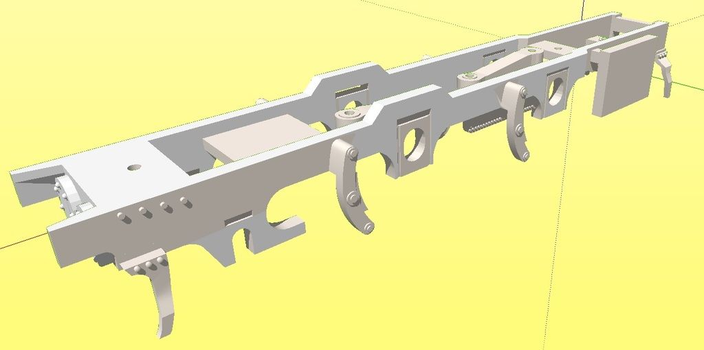
Ok, well I've been having a play. What I am showing you doesn't mean it will be made but I might try it as these are preliminary improvements and trials.

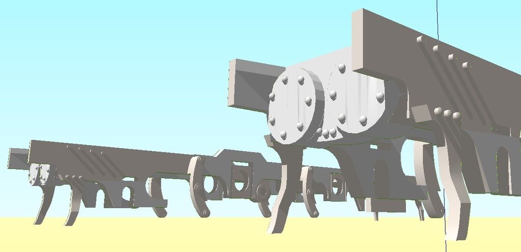
The first picture shows the front leading wheel holes opened out downwards Also the frame has been pulled upward at the front for added strength when/if the hornblock space is cut out. The rear can't have it due to the body though.
Image
The driving axles have been given downward ovals now as I was thinking and the same applies.
Image
The second picture however is another idea. I must stress I am not making my own plastic hornblocks. I trialed that with both WSF and FUD in the earlier days before I let everyone know what I was up to with SCC. Thought I'd try it though and know exactly what could and couldn't be done with the materials. Reason as expected was due to friction and filing for a smooth slide made everything too loose, so the idea was shelved in favour of fitting proper brass ones.

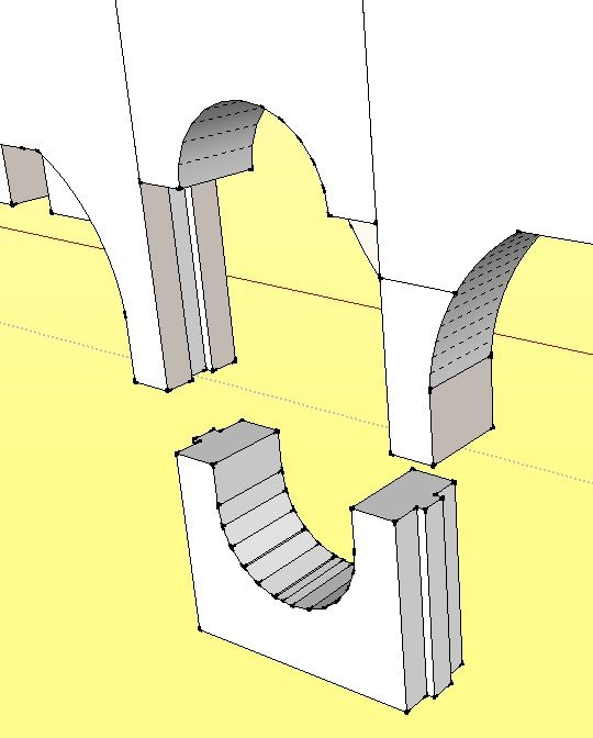
What you see here is the rectangular holes for brass hornblocks 100% cut out read and optional non horn block fillers added. The slide rails are not so they can slide up and down freely as already stated (it doesn't work in these materials) but it is simply for accurate locating and a twist resistor. The top sections are simply half curves for the bushes and the bottom sections are the same only you will notice it protrudes upwards 1mm so when in place it will be an oval. Alternative bottoms have also been done where it a makes a complete circle.

If I was to trial this and release it then maybe have a different shop section called Sprung Chassis or something.

If it works then this latter version should easily give the option of fixed or oval axle holes and a space already cut out for brass hornblocks from the off, and either way you look at it you could get the wheels in and out out a 100 times easier (was suggested to me a while back) Just would need a small retainer making. I was going to bore holes in for rod but we got the printing tolerance issue stopping it so a bit of scrap etch lightly tack glued I'm sure would work wonders.
Let me know what you think, worth trying out I reckon. If it goes to plan then adding springing or compensation or other should be straightforward. CSB not yet considered as the fulcrum positioning is a variable consideration...quite literally.


3rd picture shows the cylinder covers already integrated. The 00 ones will have to have the sides chopped sadly but what can you do? Got a P4 one in the post to plug into this prototype J1 chassis anyway.
Image
Last edited by Knuckles on Sun Oct 16, 2016 4:48 pm, edited 1 time in total.
“He who dares not offend cannot be honest.” Thomas Paine

https://www.sparkshotcustomcreations.com/
Mostly 3D Printed Loco kits etc.

SCC Price list (7/4/22)
https://www.sparkshotcustomcreations.co ... e77d42.pdf

Philip Hall
Posts: 1953
Joined: Mon Aug 10, 2009 7:49 pm

Re: Furness J1 Class - New Springy Experiments?

Postby Philip Hall » Sun Oct 16, 2016 4:40 pm

Your second picture is quite interesting, as it gives options, either for rigid axles, proper hornblocks (to fit whatever kind of suspension you wish) or merely just a little bit of downward movement. My only reservation about just a little downward movement is one you have alluded to previously, that the bearings can revolve in the chassis moulding, which will eventually wear although at first it will work.

Philip

User avatar
Knuckles
Posts: 1262
Joined: Fri Nov 18, 2011 9:15 pm

Re: Furness J1 Class - New Springy Experiments?

Postby Knuckles » Sun Oct 16, 2016 4:58 pm

Wear is a consideration indeed. After some use things might wear or they might not depending on material used. Problem is unless I rag one to death on a rolling road it is hard to know.

I could print the removable half bush retainers in brass and then the brass bush inside moving 1mm or so would be durable for sure, the price however may be a bit of a pig but I design the rectangular cut outs to convention so they could be a secondary option in the spares section that can fit everything, then one could simply choose the parts wanted as an option.

The main consideration as you say is the ovals so really only these would benefit as a brass option I would think.

One thing I haven't mastered yet is getting the wheels on square and removing them safely. Sometimes I do sometimes I don't even with the GW Models tools, although they make life easier.

People have suggested to me to find a way to make axles removable and this I currently feel would also serve that purpose quite easily. Assembling wheel sets square would be easier without a chassis sandwiched between the press.
“He who dares not offend cannot be honest.” Thomas Paine

https://www.sparkshotcustomcreations.com/
Mostly 3D Printed Loco kits etc.

SCC Price list (7/4/22)
https://www.sparkshotcustomcreations.co ... e77d42.pdf

User avatar
Knuckles
Posts: 1262
Joined: Fri Nov 18, 2011 9:15 pm

Re: Furness J1 Class - New Springy Experiments?

Postby Knuckles » Mon Oct 17, 2016 2:10 pm

I had a play about spruing together some 'Hornguide Fillers' as I call them. Spruing sadly is essential as Shapeways' only allow metal products to contain 2 items per file and as this idea I am trying takes 8 parts per axle they need to be sprued.

What is strange is the Steel versions are a lot cheaper than the brass! Would this wear out the bush though? I doubt it would enough to be a bother, using the cheaper non metal materials would likely be fine but if you are worried about wear this could be an option.

Will finish the P4 chassis revise off and have a go. Pretty exited I am.

Think I'll order some steel and wsf ones and see how we get on. If it all works out plan is to do new chassis (or revise old ones) with the fillers in the same file and then metal ones or replacements can be brought on the side as options.

So far oval ones have been made and also circular ones for fixed axles. Might do a third option where the centre point is moved to account for both up and down movement although there would have to be used with a proper form of compensation or springing.

How much up or down movement would be required? Thinking 0.7 up and same down? So 1.4 in total or maybe just .5 each way so 1mm in total?  1mm each way thus 2mm?

I understand this is a matter of choice so custom tweaks could easily be done on request but it would be good to start with a fixed ideal.
“He who dares not offend cannot be honest.” Thomas Paine

https://www.sparkshotcustomcreations.com/
Mostly 3D Printed Loco kits etc.

SCC Price list (7/4/22)
https://www.sparkshotcustomcreations.co ... e77d42.pdf

Philip Hall
Posts: 1953
Joined: Mon Aug 10, 2009 7:49 pm

Re: Furness J1 Class - New Springy Experiments?

Postby Philip Hall » Mon Oct 17, 2016 2:21 pm

I believe that the general rule for bushes and axles and the like is that they should be of dissimilar metals, i.e. Brass or phosphor bronze bushes with steel axles. I don't think that steel bushes and steel axles is too good an idea, but there will be others on here who know more about the metallurgy stuff than I do. If the axle is to run in a brass bush inserted into your axle 'keeper' that would be fine. If it runs in effectively a slot (your oval) then it would be useful to have some means of preventing the bush from rotating in the keeper, just allowing it to move up and down, as with a conventional hornblock.

I suppose that brass axles could be made up to go with steel bushes, but brass is not really hard enough to do a good job long term as a driving axle. Brass is used for vehicle axles though, often in the USA where steel axles interfere with the trackbed magnets used for Kadee couplings, creating drag.

Philip

User avatar
Knuckles
Posts: 1262
Joined: Fri Nov 18, 2011 9:15 pm

Re: Furness J1 Class - New Springy Experiments?

Postby Knuckles » Mon Oct 17, 2016 2:36 pm

Thanks for the info. :)

I think maybe you partially misunderstand though, to clarify the plan is to still use conventional 1/8th top hat bushes made in brass but run them in the two part removable carriers that I have for now dubbed 'Hornguide Fillers,' seeing as they seem to be a new invention somewhat (not saying I'm the first.) This way the bush would be trapped in them (and easily removed) and for the oval ones the brass bush could slide up and down in the WSF, FUD, FXD, Brass, Steel, Polished Bronze Steel, Hornguide Fillers.

If rotation would be an issue that is when the fillers could be dispensed with and proper hornblocks of whatever type inserted instead.

Maybe Hornguide Bush Retainers would be a better name? Shorter name better for the website though.
“He who dares not offend cannot be honest.” Thomas Paine

https://www.sparkshotcustomcreations.com/
Mostly 3D Printed Loco kits etc.

SCC Price list (7/4/22)
https://www.sparkshotcustomcreations.co ... e77d42.pdf


Return to “Steam Locomotives”

Who is online

Users browsing this forum: ClaudeBot and 1 guest