CSB Sprung Fell Locomotive

down_under
Posts: 34
Joined: Mon Jul 15, 2019 5:25 am

CSB Sprung Fell Locomotive

Postby down_under » Tue Dec 28, 2021 1:45 am

Hi All,

First time posting, but plenty of time spent reading. I have a couple of questions for the brains trust regarding springing options for a Judith Edge "Fell" Locomotive.

I'll be building the Fell in its late look guise with the central coupling rod removed in essence making it a 4-4-4-4 (but sill a 2-D-2). As this image from Wikipedia shows:

Image

To get power to both sets of coupled wheels, there will be the special High Level drive stretcher between the two central coupled wheels giving power to both pairs of coupled wheels. This brings me to the question of CSB's. From the view point of suspension I think that I have two options:

CSB Option 1
Build as a 0-8-0 with single CSB
Fell_080_CSB.PNG

(these are my early working scribbles)

CSB Option 2
Build as a pair of 0-4-0 units
Fell_040_CSB.PNG


My main question focuses on the impact of the drive stretcher coupled between the the two sets of wheels and the effect on a 0-8-0 set up.
- Will it have any effect? will it cause some sort of bias to the way the CSB work having the two central wheels coupled?
- Would the better option be the twin 0-4-0 set up with the drive stretcher acting more like compensation between the two coupled sets of wheels?

Cheers

James
You do not have the required permissions to view the files attached to this post.

down_under
Posts: 34
Joined: Mon Jul 15, 2019 5:25 am

Re: CSB Sprung Fell Locomotive

Postby down_under » Tue Dec 28, 2021 9:57 am

CSB location as a 0-8-0 mocked up onto scan of the JE sketch
Fell_080_CSB_JE.PNG


CSB Calcs set up as 0-8-0 coupled unit
Fell_CSB_Calc_080.PNG


CSB location as 2 x 0-4-0 mocked up onto a scan of the JE sketch
Fell_040_CSB_JE.PNG


CSB Calcs set up as 2 x 0-4-0 coupled unit.I've assumed that a all the weight will be split between the two sets of coupled wheels.
Fell_CSB_Calc_040.PNG


I've ignored the bogies, these will carry some weight - I can adjust the CSB wire accordingly / springing of the bogie units. The bulk of the weight is over the coupled wheels
You do not have the required permissions to view the files attached to this post.

User avatar
Will L
Posts: 2527
Joined: Sun Jul 20, 2008 3:54 pm

Re: CSB Sprung Fell Locomotive

Postby Will L » Tue Dec 28, 2021 1:19 pm

down_under wrote:...I have a couple of questions for the brains trust regarding springing options for a Judith Edge "Fell" Locomotive.


Hi James,

Thats am interesting question. I would have said the key issue her if whether the drive stretcher arrangement between the two central axles leave them free enough to move as the suspension dictates. If you can achieve that I'm reasonable sure both set ups would work.

The advantage of the 2x2 arrangements is that anybody who is worried by the spread sheet can manage without it, as more or less any symmetrical position for the fulcrums points will be ok so long you apply the same to both 2 axle pairs. But clearly you don't have a problem with the spreadsheet. I only use the 2 axle spread sheet to calculate the wire size needed once I know the final weight.

The purest in me would favour the 4 axle set up as this is a slightly less complicated build (one less fulcrum point o worry about). Despite a few who suggest CSBs are only suited to 0-6-0s my 2-8-0 works very nicely thank you.

In either case the loco's Centre of Gravity needs to be over the centre of the driving wheels and either CSB choice will distribute the weight evenly across all four axles.

I think the choice is yours and do let us know how you get on.

down_under
Posts: 34
Joined: Mon Jul 15, 2019 5:25 am

Re: CSB Sprung Fell Locomotive

Postby down_under » Tue Dec 28, 2021 4:00 pm

Hi Will, thanks for your reply and thoughts.

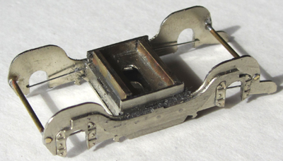
The drive stretcher in theory should 'float; between the two axles. Here it is roughly assembled before solder and tidying up:

Fell_Stretcher.jpg


Hopefully that should allow free independent movement between the two centre axles. A HL roadrunner with torque link will be required on one. I'm not sure if I go with 8 coupled CSB if I need to make the centre two slightly lighter than the 24.5%? (As per the suggestion on the CLAG digest pages). Do you think It should be slightly less given potential for resistance from the drive stretcher , or am I overthinking it?

The coupled wheelbase equates to 50% of the total wheelbase, with the weight split 25-50-25 (bogie-coupled-bogie). The main weight (lead sheet) is in the body over the coupled wheels, so that should help to keep the CoG in the right place.

Cheers,

James
You do not have the required permissions to view the files attached to this post.

User avatar
Will L
Posts: 2527
Joined: Sun Jul 20, 2008 3:54 pm

Re: CSB Sprung Fell Locomotive

Postby Will L » Tue Dec 28, 2021 10:59 pm

down_under wrote:..I'm not sure if I go with 8 coupled CSB if I need to make the centre two slightly lighter than the 24.5%? (As per the suggestion on the CLAG digest pages). Do you think It should be slightly less given potential for resistance from the drive stretcher, or am I overthinking it?

As we don't chose to make any allow for the motor, the driven axle caries more weight than the rest, but this doesn't have any impact on the suspension performance.

Either the connection between the 2nd and 3rd axle leaves them to move up and down freely of you have a problem.

Personalty I have become less worried about centre bias and I think we have been overly concerned about this in the past, even on a six wheel chassis. I now think it would need to be significantly harder on the centre axle before you started to see a problem. I care even less on an 8 wheeler although I would want the centre two to be very similar.
The coupled wheelbase equates to 50% of the total wheelbase, with the weight split 25-50-25 (bogie-coupled-bogie). The main weight (lead sheet) is in the body over the coupled wheels, so that should help to keep the CoG in the right place.

Now I've had time to think about it, the biggest problem I can think of is how you ensure you get equal weight on the bogies. I would be very tempted to make the bogies themselves heavy enough to ride well and not put any loco weight on them at all.

davebradwell
Posts: 1181
Joined: Fri Jan 18, 2019 3:48 pm

Re: CSB Sprung Fell Locomotive

Postby davebradwell » Wed Dec 29, 2021 12:27 pm

Getting the wheelbase of the Drivestretcher to match the axle centres will be the first construction hurdle as any small error will influence the actual position of the axles with respect to the hornblocks or they might even jam. This gearbox needs to twist so a challenge there, although a 26mm fixed unit isn't going to go far astray. I hope you are putting the hornguides in the outside frames - no-one ever does this properly and fly-cranks work much better without clearances in inside brgs being magnified by extended axles. Suggest vertical tab on top of reduction gearbox as easiest way of resisting torque without introducing side effects. You might consider separating motor and gearbox and joining with a Carden shaft - rtr manufacturers are doing this occasionally. Motor can be soft mounted to further reduce noise - this makes quite a difference.

To get the springs the same strength on both bogies, just make them as a pair to give same spring deflections in the same way that csbs on each side of model are matched. With sprung bogies you can model the rather prominent slides correctly with the bogie frames following the vertical movement of the loco frames. Spring each side, single support in centre of spring works well enough.

Will add that this thing is going to be very heavy so distribution of weight between axles is unlikely to matter much - they'll all have enough to stay on the track.

DaveB

User avatar
zebedeesknees
Posts: 334
Joined: Mon Jul 12, 2010 5:15 pm

Re: CSB Sprung Fell Locomotive

Postby zebedeesknees » Wed Dec 29, 2021 12:48 pm

Will L wrote:
down_under wrote:.
The coupled wheelbase equates to 50% of the total wheelbase, with the weight split 25-50-25 (bogie-coupled-bogie). The main weight (lead sheet) is in the body over the coupled wheels, so that should help to keep the CoG in the right place.

Now I've had time to think about it, the biggest problem I can think of is how you ensure you get equal weight on the bogies. I would be very tempted to make the bogies themselves heavy enough to ride well and not put any loco weight on them at all.


My way would be to look at the weight diagram of the loco, and do my best to get the proportions as close as possible. I don't think I have seen one for the Fell. Without this data my instinct from other weight diagrams is to aim to get the weight on a (sprung - of course) bogie about the same or a little less than the lightest loaded driven axle. The split would then become something like 16-68-16, with the bogies capable of leading the drivers into curves. And there will be more weight on the drivers for traction.

The CSB arrangement; I would go for the easiest. There are three options that I can see, or have tried so far, the haulage being near enough the same. There is the full 8-coupled, the 0-4-0 pairs with outer fixed fulcrums, or the pairs with simple springy equalising beams, like compensation but sprung.

The High Level 'Fell Drive Coupler' can be supported with the motor on the two axles 2 and 3, and does not need a torque reaction link. the entire assembly can float on those axles and ride with the suspension. As the weight of the motor/gearbox assembly is unsprung, it will add a small amount of tractive weight to the axles, but have no effect on the loco suspension system.

Ted.
(A purists' purist)

davebradwell
Posts: 1181
Joined: Fri Jan 18, 2019 3:48 pm

Re: CSB Sprung Fell Locomotive

Postby davebradwell » Fri Dec 31, 2021 6:59 pm

Yes Ted, I missed the trick of joining the frames of the reduction gearbox and drive coupler - I was trying to avoid commenting on this standard diesel device as I've never used one. Torque reaction might be less favourable than normal, however, due to short wheelbase and (I suspect) larger wheels. Where's Mr Penberth when he's needed? It's interesting that the prototype coupling rods are in alignment so there is presumably a geared link unless the fitter has only just removed the rods. Wonder how it was supported?

I'll stick with my constructive comments re other mechanical arrangements in my continued campaign to encourage improvements to the breed. In particular the need for sufficient clearance in the drive link to allow the hornblocks to define the wheelbase for the coupling rods. Nobody's mentioned gear ratio.....

Happy New Year to those down-under.

DaveB

User avatar
zebedeesknees
Posts: 334
Joined: Mon Jul 12, 2010 5:15 pm

Re: CSB Sprung Fell Locomotive

Postby zebedeesknees » Fri Dec 31, 2021 7:32 pm

davebradwell wrote:Yes Ted, I missed the trick of joining the frames of the reduction gearbox and drive coupler

So did I until I looked at the High Level website and found the coupler specific to the Fell! I wondered how the Drive Stretcher was going to work in the original post...

- I was trying to avoid commenting on this standard diesel device as I've never used one. Torque reaction might be less favourable than normal, however, due to short wheelbase and (I suspect) larger wheels.

I can't see how, surely the torque reaction is resisted by the other axle if the motor and gearbox are floating between them?

Where's Mr Penberth when he's needed?


Doing bogies for Warships and D8000s, I wish...

Ted.
(A purists' purist)

User avatar
grovenor-2685
Forum Team
Posts: 3923
Joined: Sun Jun 29, 2008 8:02 pm

Re: CSB Sprung Fell Locomotive

Postby grovenor-2685 » Fri Dec 31, 2021 7:56 pm

davebradwell wrote: It's interesting that the prototype coupling rods are in alignment so there is presumably a geared link unless the fitter has only just removed the rods. Wonder how it was supported?

Indeed the Fell gearbox linked all 4 main engines to both inner axles, the centre set of rods were in parallel with the gearbox which no doubt caused odd stress and wear problems leading to their removal.
Given the large mass of the gearbox I would assume it was fixed to the mainframes with quill drives to the axles, but I'm not sure of that, the detail should be on the web somewhere.
davebradwell wrote: In particular the need for sufficient clearance in the drive link to allow the hornblocks to define the wheelbase for the coupling rods.

Clearances required should be much the same as they would have been if the rods were fitted. For the reasons above I would not recommend fitting both. :)
Regards
Keith
Grovenor Sidings

User avatar
Will L
Posts: 2527
Joined: Sun Jul 20, 2008 3:54 pm

Re: CSB Sprung Fell Locomotive

Postby Will L » Sat Jan 01, 2022 11:51 am

zebedeesknees wrote:
davebradwell wrote:Yes Ted, I missed the trick of joining the frames of the reduction gearbox and drive coupler

So did I until I looked at the High Level website and found the coupler specific to the Fell! I wondered how the Drive Stretcher was going to work in the original post...
You and me both

down_under
Posts: 34
Joined: Mon Jul 15, 2019 5:25 am

Re: CSB Sprung Fell Locomotive

Postby down_under » Sun Jan 02, 2022 12:31 pm

Thanks for all the replies Dave, Ted, Will and Grovenor,

Drive Unit
Yes, my applogies for not providing a link to the HL website

Here is the High Level Road Road Runner and Fell drive stretcher mocked up (all to be cleaned up). Yes, the gearbox and stretcher are designed to be soldered together and make a ridged unit. I suppose the two axles will act as a torque link, so I think that negates the need to remote mount the motor. That is a neat solution that I had not considered before, killing a couple of birds with one stone.

So the unit should 'float' between the two axles. I'm leaning on the 0-8-0 CBS arrangement at present.

Fell_Drive Stretcher and Road Runner.jpg


davebradwell wrote: I hope you are putting the hornguides in the outside frames - no-one ever does this properly and fly-cranks work much better without clearances in inside brgs being magnified by extended axles. DaveB


Unfortunately there is very little clearance to mount on the outside frames - less than 0.5mm between wheel face and outside of the frames. So they will have to go on the inside. I've got some slimline hornblocks to maximise the space between the frames.

Fell_Plan View_JE.PNG


davebradwell wrote: Nobody's mentioned gear ratio.... DaveB


For gear ratio, the real thing had a top speed of 70 m.p.h. Wheel diameter of 4'3". I've gone for a 34:1 and a one of Chris' coreless 132
0 motors. At full noise this will make a scale 58 m.p.h. I'm not sure what else I can do, its the lowest gear ratio they make. It will get a spin on a friends 35ft roundy - roundy layout from time to time, so it will need some top end speed, but for the most part it will be on a end to end layout.

Bogies

I was going to use a method like this to spring the front bogies:

http://www.johndarch.com/Model%20Railways/Worseter/Worseter27a.html

Image

DaveB - were you thinking of something more like this - http://www.clag.org.uk/midbogie.html (minus the ball races?). Side control should be easy enough to sort out.


The Real Thing

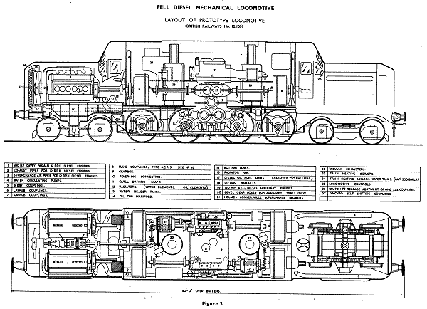
grovenor-2685 wrote:Indeed the Fell gearbox linked all 4 main engines to both inner axles, the centre set of rods were in parallel with the gearbox which no doubt caused odd stress and wear problems leading to their removal.
Given the large mass of the gearbox I would assume it was fixed to the mainframes with quill drives to the axles, but I'm not sure of that, the detail should be on the web somewhere.


Spot on - mechanical transmission bolted to the fames with quill drives on the middle two axles.

The Fell Drive Unit.PNG


Image taken from this report
The Fell.pdf


Image
You do not have the required permissions to view the files attached to this post.

davebradwell
Posts: 1181
Joined: Fri Jan 18, 2019 3:48 pm

Re: CSB Sprung Fell Locomotive

Postby davebradwell » Sun Jan 02, 2022 4:37 pm

Ratio. Top speed should be calculated using half the no-load speed as this is about where max power is produced. No power is produced at max free rpm so as you add load the motor slows down. This advice from a Portescap application booklet on their range of instruument motors.

Whether you mount the motor on the gearbox or remotely is nothing to do with torque reaction. Just a suggestion to make a quieter model.

Bogie. I see now that it has outside beams so Ted's arrangement represents this action very well. Your other photo shows a simplified arrgt, although I never use axleboxes and hornguides on a bogie, just slots in frame. Not a fan of cantilever springs either so would just put a simple centre supported spring each side, perhaps even just resting on the axles. Key thing is that wide flat plate attached to loco frame rests on plate on bogie frame - these should copy the prototype to get correct appearance. The tempting alternative single centre spring performs relatively poorly and does nothing to keep loco upright. Wouldn't bother with side control but if you're tempted the CLAG type should be improved to provide a pre-load like the real thing.

Pity about the outside hornguides but correct width of loco frames is essential to the character of the beast.

I was surprised how small the wheels were on a loco of this age.

Still not convinced where Ted's torque is going but I'm sure it will work well. I'll stew on it for a few weeks.

DaveB

User avatar
zebedeesknees
Posts: 334
Joined: Mon Jul 12, 2010 5:15 pm

Re: CSB Sprung Fell Locomotive

Postby zebedeesknees » Sun Jan 02, 2022 5:04 pm

down_under wrote:Thanks for all the replies Dave, Ted, Will and Grovenor,

Thank you James for such an interesting post!
DaveB - were you thinking of something more like this - http://www.clag.org.uk/midbogie.html (minus the ball races?). Side control should be easy enough to sort out.

The ball races in that bogie were to minimise the friction, there were more in the tender. With a single driver, I felt the need..
That inspired the design for the 2P:-
http://www.clag.org.uk/class2p-bill.html

This design is really just a reduction to 4mm scale of the dynamics of the S.W.Johnson bogie design for the Midland Railway, which was subsequently used by many, including the L.M.S. and even B.R. Standard classes. Also from the drawing - the Fell.

Image taken from this report The Fell.pdf

Thanks for that, a fascinating read. I skip-read it in the hope of finding a weight diagram, but have yet to find one specific to 10100. Nor is the overall weight of the loco mentioned afaics. However, the 'proposed' express passenger 4-8-4 shown on P.247 does have weights, and my suggestion that the bogies should carry about the same as a single driving axle was close. I suspect that it would have been closer, but the overall weight adds up to 120 tons, and Bridge Stress Committees of the time would have restricted the routes available to a loco with an axle weight in excess of 19 tons.
For the model I would stick to my split of 16-68-16 if possible.

Ted.
(A purists' purist)

User avatar
Will L
Posts: 2527
Joined: Sun Jul 20, 2008 3:54 pm

Re: CSB Sprung Fell Locomotive

Postby Will L » Sun Jan 02, 2022 5:09 pm

down_under wrote:... I suppose the two axles will act as a torque link...
Err, no.
Imagine that for some reason one of the driven axles can't turn. The motor unit will now try and revolve round that axle and that in turn will force the other axle up or down (depending on which direction its trying to go in). In reality, rarely will anything as dramatic as that happen. A good free running chassis may well show no signs of needing a reaction link, that is, until the day something jams, or you hang a very heavy train on the drawbar. However, a stiff chassis may well show odd behaviour all the time. I would have said this arrangement needs a torque reaction link (or links, see below) more than a single driven axle.

Solutions. A DaveB style reaction link, i.e. a vertical tab on the top of the gear box running into a slot attached to the body above the motor is probably an adequate, although not a theoretically perfect, remedy. Better still a single vertical tab fixed centrally above the drive unit. Best of all have two separate vertical tabs with each one directly above an axle. This would really ensure the whole unit could only rise and fall and not turn. But I agree no need to remotely mount the motor.

User avatar
zebedeesknees
Posts: 334
Joined: Mon Jul 12, 2010 5:15 pm

Re: CSB Sprung Fell Locomotive

Postby zebedeesknees » Sun Jan 02, 2022 5:27 pm

Will L wrote:
down_under wrote:... I suppose the two axles will act as a torque link...
Err, no.

I have to disagree with you there Will.
Nothing wrong with the theory, but I suggest that the magnitude is not significant, especially with the motor weight on the stretcher. Yes, under load one axle will be driven upwards and the other driven down, but to all 'intents and purposes' these will cancel as far as traction is concerned.
My suggestion to James is to be prepared to have to introduce a separate reaction link if it proves to be needed, but resist the complication until then.

Ted.
(A purists' purist)

User avatar
Will L
Posts: 2527
Joined: Sun Jul 20, 2008 3:54 pm

Re: CSB Sprung Fell Locomotive

Postby Will L » Sun Jan 02, 2022 7:37 pm

zebedeesknees wrote:
Will L wrote:
down_under wrote:... I suppose the two axles will act as a torque link...
Err, no.

I have to disagree with you there Will.
Nothing wrong with the theory, but I suggest that the magnitude is not significant, especially with the motor weight on the stretcher. Yes, under load one axle will be driven upwards and the other driven down, but to all 'intents and purposes' these will cancel as far as traction is concerned.
My suggestion to James is to be prepared to have to introduce a separate reaction link if it proves to be needed, but resist the complication until then.

You're not really disagreeing Ted, you're saying you don't believe that, in most circumstances, the lack of a link will not have any noticeable effect, a point of view which I did cover. On most chassis you only find out what the lack of a the torque reaction link does when something else goes wrong. I once spent a lot of time trying to diagnose he running problems of a loco which persistently lifted one wheel off the track once per revolution. The presence of a torque reaction link would have made it much clearer where the real problem lay.

User avatar
Will L
Posts: 2527
Joined: Sun Jul 20, 2008 3:54 pm

Re: CSB Sprung Fell Locomotive

Postby Will L » Sun Jan 02, 2022 8:20 pm

down_under wrote:.... Side control should be easy enough to sort out....

I have what some may thing are heretical views about the the fitting, or not, of side control springs. To get the best of what I sort of hope may prove to be an interesting discussion I have posted my views else where under a new thread entitled
Is there any need for side control springs on loco bogies and pony trucks?
Enjoy

davebradwell
Posts: 1181
Joined: Fri Jan 18, 2019 3:48 pm

Re: CSB Sprung Fell Locomotive

Postby davebradwell » Sun Jan 02, 2022 9:06 pm

You've helped me shorten my weeks of pondering, Will, and the drive link will certainly influence one axle up and one down. The effect will be greater with heavy loads. The problem is I can't see what can be done about it - the mid wheelbase tab will take the torque well enough but then these axles won't be able to rise and fall with respect to each other and if the tab is a tiny bit out of position, one axle will be lifted. The consolation is most diesels seem to work something like this - wish I'd taken more notice.

Side control helps bogies and pony trucks derail on sharp curves unless they carry a huge amount of weight. Furthermore, unless the springs are designed properly they do nothing to prevent the loco slewing on straight track. Think of a model joystick - it has a positive centre position and a preload must be overcome before the stick can be moved. Let go and it snaps back to the centre. This is the way side control works on the prototype, there has to be a pre-load acting against a stop and bogie movement pushes against the stop from the other side. I can't see any point in anything less. Here is my design for this and the drg also shows my springing for the simpler Thompson bogie:

Image (30).jpg


There will be many other ways, or course.

Just to be clear, I never said the remote motor was essential to any mechanical function. It's a nicety but produces a quieter, smoother running loco and enables the worm shaft to be fitted with decent thrust brgs.

DaveB
You do not have the required permissions to view the files attached to this post.

User avatar
zebedeesknees
Posts: 334
Joined: Mon Jul 12, 2010 5:15 pm

Re: CSB Sprung Fell Locomotive

Postby zebedeesknees » Mon Jan 03, 2022 6:21 pm

Will L wrote:You're not really disagreeing Ted, you're saying you don't believe that, in most circumstances, the lack of a link will not have any noticeable effect, a point of view which I did cover.

After a ponder on this in the shower this morning, (yes it works for me too Will!) in the case of the Fell, I am re-thinking the forces..

Considering the forces on the stretcher, remember that two axles, one at either end, are driven by a common gear train. So any reaction caused by a torque spike will apply to both ends of the stretcher.

Now, consider the reactions about one of the axle gears in isolation: When it's rotation is inhibited in some way, the stretcher will try to move the opposite way about the axle. Were the axle central in the stretcher, one side of it would want to move upwards, but the other side would want to move down.

Since the two gears on axles are in unison, (unless there is something very wrong!) then the one trying to push the stretcher up from one end will be opposed by the one at the other end pushing down, and the effect on each axle would just about double, one axle being unloaded and the other loaded by the same degree.

Another point - considering the magnitude of the force at the opposite end of the stretcher, ignoring the existence of the other gear, axle,and motor weight - is the length of the lever. The H/L final drive gear has a pcd of 8mm, so a radius of 4. Therefore, the torque force at the other end of the stretcher will be 4/26 or less than one sixth of that at the gear.

So with the weight of the motor on the stretcher, my opinion is that the torque reaction will neither lift an axle nor have any noticeable effect on traction. Should it cause a problem, the design of a reaction control linkage to prevent this will be interesting...

On most chassis you only find out what the lack of a the torque reaction link does when something else goes wrong. I once spent a lot of time trying to diagnose he running problems of a loco which persistently lifted one wheel off the track once per revolution. The presence of a torque reaction link would have made it much clearer where the real problem lay.


One wheel? Hmmm...
My introduction to the torque reaction effect was years ago with a DJH 7F; It is fitted with two pairs of springy beams and an RG4 driving the 3rd axle, the motor pointing backwards in the firebox. The first effect was a noticeable clonk on change of direction, but not enough to cause me to investigate.
Haulage with a heavy test train was great running forward, but under load in reverse the rear axle would lift clear of the rails by 1mm or more. What was happening was the motor was trying to rotate about the 3rd axle in the opposite direction and was pressing against the top of the firebox, the leverage pressing the 3rd axle down and lifting the 4th clear.
The solution was a horizontal hinged link on the gearbox, to a hinged fixed point on the chassis. Now the reaction forces in either direction have no effect on the axle loads.

Ted.
(A purists' purist)

davebradwell
Posts: 1181
Joined: Fri Jan 18, 2019 3:48 pm

Re: CSB Sprung Fell Locomotive

Postby davebradwell » Mon Jan 03, 2022 9:32 pm

I'm having trouble with this too, Ted, but I can't agree with you ..... yet, although I'd like to. Perhaps you can put a different argument.

First, the weight of the motor has nothing to do with it. Axles are held down by springs and small motor weight just adds a little to this.

Here's my latest line on this: I use a lot of Roadrunner+ gearboxes and it's essential to solder the frames of the trailing arm and main 'box together or it just jumps about. This soldered up unit is directly equivalent to the Fell box and if I don't restrain the torque with a tab it does exactly the same as your 7F so there is a reaction if it's driving something.

Imagine I take the idler shaft out of the corner of my Roadrunner and put in an axle - I now have a 4 wheeled unit which would scoot about (yes it would need another idler but never mind) quite happily. We might add a Drivestretcher and as long as we soldered the frames together it would still scoot around. With unattached frames it's exactly like the floating Fell box or my unsoldered gearbox and there will be a torque reaction depending on what it's pulling and it will bend in the middle. Your Fell box will try to rise at one end and fall at the other because it's trying to rotate if it's not fixed to the frames. It is likely that with appropriate weight for the load pulled this won't be a problem.

I can't see that the gear size is part of the equation, wheel diameter probably. It's a torque so smaller gear = bigger force.

A useful fall-back is, if in doubt copy the prototype. This has box fixed to frames but I suspect the complication of the quill drives might not appeal.

Actually, if the outer axles carried no weight, and therefore required no torque to drive them, wouldn't that sort it as it's back to my 4w unit running about? Or is this another step towards an understanding?

DaveB

User avatar
grovenor-2685
Forum Team
Posts: 3923
Joined: Sun Jun 29, 2008 8:02 pm

Re: CSB Sprung Fell Locomotive

Postby grovenor-2685 » Mon Jan 03, 2022 10:33 pm

Surely the torque reaction is trying to turn the motor and gearbox around the driven axle, so you need a restraint vertically above the axle to stop the motor moving fore and aft, ie only allowing vertical movement, just like any other gearbox installation, the second axle on the link is irrelevant, except you just need a small flexibility allowance for the two axles being at slightly different levels when going over bumps.
IMHO there should be no need to fix the link to the gearbox, it would be better if they were seperate, the link is only acting as a pair of coupling rods.
Regards
Keith
Grovenor Sidings

davebradwell
Posts: 1181
Joined: Fri Jan 18, 2019 3:48 pm

Re: CSB Sprung Fell Locomotive

Postby davebradwell » Tue Jan 04, 2022 9:40 am

Haven't you just taken us back to where we started, Keith.

Moving on from my last ramblings, I've got it at last. With equal weight on all axles again we have a self contained 4 wheel chassis with extenders each end. Because each of these is only transmitting a quarter of the total torque the vertical reaction is much less than the spring force holding it down by somewhere between 10 and 40, depending on rail friction.

There must be a similar counter reaction tipping the 4w unit but same argument applies. Not soldering the drive stretcher to the gearbox means you''re dealing with a higher torque so worse reaction. Suspect this argument applies to all similar combinations of gearbox like Roadrunner+ or adding Drivestretcher.

You had to be right, Ted, because you've built far more things like this than I have and you said it would work.

We can just sit back now and await a vid of the completed model.

DaveB

User avatar
grovenor-2685
Forum Team
Posts: 3923
Joined: Sun Jun 29, 2008 8:02 pm

Re: CSB Sprung Fell Locomotive

Postby grovenor-2685 » Tue Jan 04, 2022 1:02 pm

davebradwell wrote:Haven't you just taken us back to where we started, Keith.


Just trying to get back on track, it was all getting way to confusing.
We have an 0-8-0 drive.
The gear coupler between 2nd and 3rd axles is just a substitute for coupling rods.
So just fit the motor drive as you would for any other 0-8-0 ignoring the gear coupler.

Fixing the gear coupler to the gearbox is creating unneccessary constaints, which is not to say it won't work. :)
Regards
Keith
Grovenor Sidings

davebradwell
Posts: 1181
Joined: Fri Jan 18, 2019 3:48 pm

Re: CSB Sprung Fell Locomotive

Postby davebradwell » Tue Jan 04, 2022 3:11 pm

I nearly went with you there Keith and had even written a humble confession - both the gears and coupling rods transfer rotation so appear equivalent. Surely, though, coupling rods act horizontally so can't lift or depress an adjacent axle whereas gears interact vertically and impart a significant vertical force to the driven and an opposite reaction to the driver.

I trust Ted and Will aren't flagging.

Don't think I'll be able to cope with building a chassis ever again!

DaveB


Return to “Chassis and Suspensions”

Who is online

Users browsing this forum: ClaudeBot and 0 guests