Hi All.
I'm still battling away with a Brassmaster 4F and have come up against a problem. The chassis runs freely with the rods on {even with the inside motion fitted till one of the drop links broke}. So I decided to crack on with getting the chassis ready for paining and finishing off. I also decided to get the basic body built to check clearances and fitting etc. This is when the first problem arose. The rods were fouling the underside of the running plate {footplate}, this led to me realising that the ride height is too low. If you don't know the hornblocks are secured and sprung by a piece of spring wire running the length of the chassis anchored either side of each hornblock and the hornblock itself. So there's no real means of adjusting the ride height that I can see.
The only way I can think make the ride height higher is to have some small springs on top of the hornblocks which will push the frames up. But the problem there is the front two hornblocks and hornblock guides have been cut back to make room for the slide bars and so there's very little surface area to support a spring.
Any Ideas please!!
Help with a Brassmasters 4F
-
Will L

- Posts: 2524
- Joined: Sun Jul 20, 2008 3:54 pm
Re: Help with a Brassmasters 4F
Dave
I've met a working version so it ought to work. Think we may need some pictures to find out how well your build matches the instruction diagram
repeated below

P.s. in case anybody is wondering this isn't a CSB, despite having Continuous Springy Beams. It is more closely related to individual springs per axle, but quite what the effect of using one continuous wire is I wouldn't like to say.
I've met a working version so it ought to work. Think we may need some pictures to find out how well your build matches the instruction diagram
repeated below
P.s. in case anybody is wondering this isn't a CSB, despite having Continuous Springy Beams. It is more closely related to individual springs per axle, but quite what the effect of using one continuous wire is I wouldn't like to say.
-
Andy W

- Posts: 884
- Joined: Thu May 21, 2009 8:11 am
Re: Help with a Brassmasters 4F
How much higher does the footplate need to be? Is using strips of plasticard to raise the height a possible solution?
Make Worcestershire great again.
Build a wall along the Herefordshire border and make them pay for it.
Build a wall along the Herefordshire border and make them pay for it.
-
Will L
- Posts: 2524
- Joined: Sun Jul 20, 2008 3:54 pm
Re: Help with a Brassmasters 4F
Like I said I've met at least one of these built and running by John Sherratt of this manor (see this CAG meeting reports from 2010). Given that one of the people behind brassmasters is also a member of CAG and attended the above meeting, I think I'd know if there was a problem with the kit.
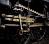
The meeting report above includes the following image primarily to show the inside motion provided by this kit, but it does show the realtionship between the footplate and chassis top, and (just) the crankpins approaching the top of there throw and well clear of the footplate

To start with at least, I think we are looking for a build error. Wrong wheels for instance?
The meeting report above includes the following image primarily to show the inside motion provided by this kit, but it does show the realtionship between the footplate and chassis top, and (just) the crankpins approaching the top of there throw and well clear of the footplate
To start with at least, I think we are looking for a build error. Wrong wheels for instance?
-
Serjt-Dave
- Posts: 643
- Joined: Tue Oct 02, 2012 3:31 pm
Re: Help with a Brassmasters 4F
I quite except the fact it's something I've done rather than a problem with the kit. After all this is the first full blown loco kit I've made for many years.
I'm about 1mm too low, checking it against my buffer height gauge and the 4F's Fowler tender.
I'll take some photos and post them to see if anyone can spot my error.
Thanks.
I'm about 1mm too low, checking it against my buffer height gauge and the 4F's Fowler tender.
I'll take some photos and post them to see if anyone can spot my error.
Thanks.
-
Jol Wilkinson

- Posts: 1114
- Joined: Mon Jul 21, 2008 7:39 pm
Re: Help with a Brassmasters 4F
If the rods are striking the running plate, then do the wheels have the correct crankpin throw?
If the buffers are not at the correct 14mm height above track level, then packing between the frames and footplate seems the answer.
If the buffers are not at the correct 14mm height above track level, then packing between the frames and footplate seems the answer.
-
billbedford
Re: Help with a Brassmasters 4F
Will L wrote:P.s. in case anybody is wondering this isn't a CSB, despite having Continuous Springy Beams. It is more closely related to individual springs per axle, but quite what the effect of using one continuous wire is I wouldn't like to say.
It's an ill-tought out cludge. With CSBs any vertical movement of one axle will product a movement in the opposite direction in adjacent axles, while with this arrangement movement in one axle produces a movement in the same direction in all other axles.
-
Serjt-Dave
- Posts: 643
- Joined: Tue Oct 02, 2012 3:31 pm
Re: Help with a Brassmasters 4F
Hi All. Here are some images of my 4F. I'm using Gibson 5' 2 2/1" wheels {though they should be 5' 3"}. They have a 11" {3.66mm} throw. The spring wire used is what is supplied and is of 0.11" gauge. You'll see from the image showing the inside of the chassis from the top that the front axle is almost touching the slide bars. When the loco is finished and fully weighted this would cause the front axle to rub on the slide bars and will mean the loco will be unbalanced. I've used a Society's gauge to show you how low it is.
Sorry that the second image is upside down. I've tried turning it the other way to no avail.
Sorry that the second image is upside down. I've tried turning it the other way to no avail.
You do not have the required permissions to view the files attached to this post.
-
Russ Elliott

- Posts: 930
- Joined: Thu Jun 02, 2011 6:38 pm
Re: Help with a Brassmasters 4F
Looks like about 1mm chassis to body packing is necessary to get that buffer height respectable.
-
Jol Wilkinson
- Posts: 1114
- Joined: Mon Jul 21, 2008 7:39 pm
Re: Help with a Brassmasters 4F
So, the body is too low against the frames or the wheels/axles are too high in the frames (ride height).
I think that this is one of those times when a good drawing, preferably a GA, would help.
I think that this is one of those times when a good drawing, preferably a GA, would help.
-
Serjt-Dave
- Posts: 643
- Joined: Tue Oct 02, 2012 3:31 pm
Re: Help with a Brassmasters 4F
The marriage between the frames and body I think is correct. It's the wheels into the frames or ride height which is the problem. I might try a slightly thicker spring wire, this might help support the weight of the loco better and stop it sinking down on it's hornblocks.
-
jim s-w

- Posts: 2189
- Joined: Wed Jul 30, 2008 5:56 pm
Re: Help with a Brassmasters 4F
When the body is on is there any further movement in the suspension or has it bottomed out?
-
Serjt-Dave
- Posts: 643
- Joined: Tue Oct 02, 2012 3:31 pm
Re: Help with a Brassmasters 4F
There is movement with the centre axle, very little with the rear axle {wheels scraping the joint from splasher and cab floor}, and a nats whisker with the front axle.
-
garethashenden
- Posts: 406
- Joined: Tue Apr 07, 2015 9:41 pm
Re: Help with a Brassmasters 4F
Will L wrote:
If we compare these two images isn't there a lot more frame sticking up between the splashers? It sticks up a little bit on one and a lot on the other right? Or is the blackening hiding it?
-
Will L
- Posts: 2524
- Joined: Sun Jul 20, 2008 3:54 pm
Re: Help with a Brassmasters 4F
Looking at the pictures, you do seem to have got it together as the diagram , but I agree there must be some clearance between the axle and the cylinder slide bars, and in any event it is quite clear that the whole thing is sitting significantly too low.
I am not clear how the body sits on the chassis, am I right in thinking that it slots in behind the buffer beam at the front, and the footplate sits on top pf the chassis at the rear where the single fixing bolt is. If thats right might be tricky to adjust how they fit together at the front. Contrary to garethashenden I though your pic from above the foot plate shows perhaps only a shade more of the chassis frame sittimg above the footplate as on John S's example above, which does suggest that the suspension is sitting much to low. Shows how hard it is to interpret photos.
In theory with little weight on this sort of suspension,(i.e. up side down as you photo) the fulcrum points on the axle blocks should be held pretty much in line with the fixed fulcrum points, I wouldn't expect to see as much bending of the wires as you seem to have. The design should then ensure that the wire will be prestressed a little bit (0.5mm on a CSB) when under the full loco weight, with as last as much movement available again under a large enough load before the axle reaches the top.
Couple of questions.
How much clearance is there through the fulcrum point holes, e.g. how much smaller than the hole is the wire. These should be a good sliding fit, as a lot of clearance would reduce the ride height by twice the amount of clearance. (clutching at straws a bit that one)
Are you sure that is 11 thou spring steel wire. Comparing it with a loco which is supposed to have 12 though wires it looks a bit thin, and spring steel wire is usually bright and shiny. The axle at the cylinder end looks to be compressed a long way down with no more weight on it than the wheel and axle.
I must admit, that now I've looked hard at the instructions, and the etches on the brassmaster web site, I do wonder if it is possible to get the springs to support the axles at the level suggested by the etched axle holes.
-
Serjt-Dave
- Posts: 643
- Joined: Tue Oct 02, 2012 3:31 pm
Re: Help with a Brassmasters 4F
To me both models look about the same with the amount of frame showing between the splashers. But there again I'm the one with the problem. LOL. On my model the amount of frame showing is about 1.5mm. The body only sits on the frames at the very front and back. Here's an images from the Bassmasters instructions showing the same area.
Whilst looking for the above image I noticed that the wire they use for securing and springing looks a lot thicker that the one supplied with the kit. What do you think?
Whilst looking for the above image I noticed that the wire they use for securing and springing looks a lot thicker that the one supplied with the kit. What do you think?
You do not have the required permissions to view the files attached to this post.
-
billbedford
Re: Help with a Brassmasters 4F
Serjt-Dave wrote:Whilst looking for the above image I noticed that the wire they use for securing and springing looks a lot thicker that the one supplied with the kit. What do you think?
Agree. This is not a CSB arrangement so you can't use the spreadsheet to work out the wire thickness. What gauge of wire do Brassmasters recommend?
-
Alan Turner
- Posts: 643
- Joined: Sun Jul 20, 2008 4:24 pm
Re: Help with a Brassmasters 4F
billbedford wrote:Serjt-Dave wrote:Whilst looking for the above image I noticed that the wire they use for securing and springing looks a lot thicker that the one supplied with the kit. What do you think?
Agree. This is not a CSB arrangement so you can't use the spreadsheet to work out the wire thickness. What gauge of wire do Brassmasters recommend?
To quote the instructions: "Suspension the kit has been designed to have a sprung beam which runs the full length of the chassis. The wire
supplied is 0.011 guitar wire but we have also tried 0.014 wire."
regards
Alan
-
Serjt-Dave
- Posts: 643
- Joined: Tue Oct 02, 2012 3:31 pm
Re: Help with a Brassmasters 4F
Hi Bill. In the instruction parts list it says 0.11" guitar string and I would say that what was supplied.
Hi Will. The wire is 0.11" and it's not by any means a tight fit. If you say that it is meant to be a 0.12" wire I would say that the wire would be a tighter fit.
So it looks like I need some slightly thicker spring wire. I can pick some up this weekend at the EM Gauge Society show. I'll let you know how I get on.
Thanks
Dave
-
Serjt-Dave
- Posts: 643
- Joined: Tue Oct 02, 2012 3:31 pm
Re: Help with a Brassmasters 4F
Alan Turner wrote:billbedford wrote:Serjt-Dave wrote:Whilst looking for the above image I noticed that the wire they use for securing and springing looks a lot thicker that the one supplied with the kit. What do you think?
Agree. This is not a CSB arrangement so you can't use the spreadsheet to work out the wire thickness. What gauge of wire do Brassmasters recommend?
To quote the instructions: "Suspension the kit has been designed to have a sprung beam which runs the full length of the chassis. The wire
supplied is 0.011 guitar wire but we have also tried 0.014 wire."
regards
Alan
Hi Alan, just seen your response after I posted mine. It doesn't sound much 3 thou but it sounds like it's the difference between the loco running or not. I'll pick up several sizes and see what works the best. Thanks
Dave
-
Will L
- Posts: 2524
- Joined: Sun Jul 20, 2008 3:54 pm
Re: Help with a Brassmasters 4F
Serjt-Dave wrote:Hi Bill. In the instruction parts list it says 0.11" guitar string and I would say that what was supplied.
Hi Will. The wire is 0.11" and it's not by any means a tight fit. If you say that it is meant to be a 0.12" wire I would say that the wire would be a tighter fit.
So it looks like I need some slightly thicker spring wire. I can pick some up this weekend at the EM Gauge Society show. I'll let you know how I get on.
I'm not convinced it looks rigid enough, so as a first step I would have though substituting it would be the first step.
-
Alan Turner
- Posts: 643
- Joined: Sun Jul 20, 2008 4:24 pm
Re: Help with a Brassmasters 4F
I'm not sure quite what's going on however (and I know this is not strictly correct due to the continuous wire) but an 11thou wire spanning 16mm (is that correct?) carrying an axle load of 35gms (just how much does your loco weigh?) would deflect 0.1mm.
If this were a CSB chassis, with axle loads evenly balanced you would get 0.5mm deflection for a 100gm loco.
In other words your arrangement should result in a stiffer chassis than a CSB chassis.
so could you provide:
weight of loco
distance between spring supports
regards
Alan
If this were a CSB chassis, with axle loads evenly balanced you would get 0.5mm deflection for a 100gm loco.
In other words your arrangement should result in a stiffer chassis than a CSB chassis.
so could you provide:
weight of loco
distance between spring supports
regards
Alan
-
Steve Carter
- Posts: 644
- Joined: Tue Nov 11, 2008 6:51 pm
Re: Help with a Brassmasters 4F
Serjt-Dave wrote:Hi Bill. In the instruction parts list it says 0.11" guitar string and I would say that what was supplied.
Hi Will. The wire is 0.11" and it's not by any means a tight fit. If you say that it is meant to be a 0.12" wire I would say that the wire would be a tighter fit.
So it looks like I need some slightly thicker spring wire. I can pick some up this weekend at the EM Gauge Society show. I'll let you know how I get on.
Thanks
Dave
Hi Dave
Brassmasters are trading at expoEM so maybe you could take your loco with you and show them your problem? I've found them to be very helpful.
Cheers
Steve
Steve Carter
-
Jol Wilkinson
- Posts: 1114
- Joined: Mon Jul 21, 2008 7:39 pm
Re: Help with a Brassmasters 4F
Perhaps a bit of back to basics might be worth considering.
The photo of the buffer bodies against the gauge would seem to indicate that the loco needs raising 1.0 - 1.5 mm, rather more than a change of wire thickness might provide.
So if the position of the hornblock in the guide is too low and using thicker wire won't work or will provide springing that is too stiff, then I would be inclined to replace the BM wire retainers soldered to the hornblocks with something longer (handrail knobs perhaps).
-
Russ Elliott
- Posts: 930
- Joined: Thu Jun 02, 2011 6:38 pm
Re: Help with a Brassmasters 4F
Jol Wilkinson wrote:The photo of the buffer bodies against the gauge would seem to indicate that the loco needs raising 1.0 - 1.5 mm, rather more than a change of wire thickness might provide.
Yes. (Hence my previous suggestion.)
So if the position of the hornblock in the guide is too low and using thicker wire won't work or will provide springing that is too stiff, then I would be inclined to replace the BM wire retainers soldered to the hornblocks with something longer (handrail knobs perhaps).
Jol, this is an underslung arrangement. Putting something longer in will make the chassis even lower!!
Return to “Chassis and Suspensions”
Who is online
Users browsing this forum: ClaudeBot and 1 guest