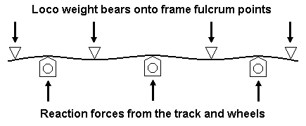
I'm just putting together my first CSB chassis and need reassurance. The spring is horizontal in the frame when the bearings are at the bottom of the hornguides. When the bearings sit at ride height the springs are deflected upwards in an arc. I assume this is correct?
For some reason I expected the springs to be horizontal at ride height, but this isn't logical now I've thought about it. I've used the High Level jig and followed the Russ's Clag templates. So I think I've got it right. Have I?
CSB newby
-
grovenor-2685

- Forum Team
- Posts: 3923
- Joined: Sun Jun 29, 2008 8:02 pm
Re: CSB newby
All correct so far, the aim is to get about 0.5mm of deflection when the model is at its design weight. This setting should not be the upper limit of travel for the hornblocks so the deflection can increase on uneven track. If needed the deflection can be modified by changing the wire diameter.
Regards
Keith
Regards
Keith
-
Andy W

- Posts: 884
- Joined: Thu May 21, 2009 8:11 am
Re: CSB newby
Thanks Keith, that sounds about right for what I've built. I think I got nervous because a lot of diagrams show the spring wires as horizontal with no arches in them. I'll push on.
Make Worcestershire great again.
Build a wall along the Herefordshire border and make them pay for it.
Build a wall along the Herefordshire border and make them pay for it.
-
Russ Elliott

- Posts: 930
- Joined: Thu Jun 02, 2011 6:38 pm
Re: CSB newby
Ealing wrote:I think I got nervous because a lot of diagrams show the spring wires as horizontal with no arches in them. I'll push on.
The sole purpose of the dimensioned plots is to indicate the longitudinal positions of the fulcrum points and axles. There are a couple of other non-dimensioned 'how it works' graphics where I perhaps could/should show the arches of the beam (which would be very overscale of course), but I hope the general principle of what is happening vertically will be understood, i.e.:

If there is a wider concern over any lack of conceptual explanation, please shout. In the meantime, I'll put a note on the CSB page indicating that the dimensioned plots do not show the deflected beam shape nor it is their intention or purpose to do so.
The vertical positioning of the 'line' for the frame fulcrum points can be counter-intuitive at first. There was an interesting exchange recently on RMweb among some of the 7mm crew ("What's all this CSB lark about, then? I might fancy some of that.") where confusion reigned about the height setting, and I did this graphic to illustrate the general strategy:
For users of Chris Gibbon's jig, the hole to be used in his carriers corresponds to the chosen lettered row on the jig. (That choice being dictated by what is convenient real-estate on the frames themselves.)
You do not have the required permissions to view the files attached to this post.
-
Andy W

- Posts: 884
- Joined: Thu May 21, 2009 8:11 am
Re: CSB newby
Thanks Russ, I can sleep easy now.
Make Worcestershire great again.
Build a wall along the Herefordshire border and make them pay for it.
Build a wall along the Herefordshire border and make them pay for it.
Return to “Chassis and Suspensions”
Who is online
Users browsing this forum: ClaudeBot and 4 guests