Those of you with long memories may remember that the "original" (real?) Alan Gibson used to produce a smallish range of brass centred loco driving wheels. My memory of this was jogged a few months ago when I bought a Gibson M.R. Compound from a certain well-known internet auction site and found, in addition to the usual range of plastic (nylon?) centred drivers, there were also four of these all-metal varieties. To someone who likes wherever possible to use split-axle/split-frame pick up these will be a real bonus when I come to build that particular kit.
The story moves on to this autumn when, perusing the latest catalogue from the "new" Alan Gibson (a.k.a. Colin Seymour), I noticed reference to "brass-centred wheel kits". For those unaware of them they are mentioned at pages 6 (driving wheels) and 7 (bogie and tender wheels). Further details can be found here - http://www.alangibsonworkshop.com/
It will be noticed that unlike previously these are referred to as "kits" and have to be made up into complete wheels. I sought out the Gibson stand at the recent Warley exhibition at the NEC and after a pleasant chat with Colin came away with enough wheels to try out on a Midland Railway 3,500 gallon tender I am building to go with a "Spinner", courtesy of London Road Models. What follows are my experiences to date over a few evenings away from party hats and mince pies.
For each set of two wheels/one axle you buy two packets - see first photo below - a yellow carded one with the two brass centres and a length of 2mm steel axle and a blue carded one with the associated turned tyre in steel. My assumption is that the steel tyres are exactly the same as used in the ordinary range of wheels and have been liberated for this new use. Colin explained to me that the brass centres have been produced by the lost wax method (if I recall correctly) and have a central hole which is deliberately cast under axle size and a diameter that is cast over size. The technique is to carefully open out the size of the hole so that it is a nice tight fit on the axle ( I used a tapered broach, removing small amounts at a time and repeated checking. Try also to keep the broach at right angles to the casting although any minute wobble that arises will be taken care of by the turning that is to follow). At this point I soldered the axle to the casting using some 180 degree stuff. ( I wanted to be sure there was a gauranteed electrical bond between the axle and wheel and also to ensure that there was no slippage for the next stage of the process). The crude wheel was then mounted on the lathe using its own axle as the mandrel and turned down, bit by bit until the steel wheel fitted. I also skimmed the face of the wheel while I was at it as the tyres go on from the front and I wanted to ensure that the back face of the tyre was proud of the slightly rough back of the casting and any wobble was taken care of. As before out came the soldering iron for round 2. And there you have it. One perfectly round, perfectly solid, electrically- conductive wheel.
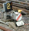
Of course this does not explain what to do about the second wheel on the axle. My less than cunning plan here, having now assembled all six wheels onto six full length axles (I ditched the plain-ended axles in favour of standard pin-pointed "wagon" axles except for the central pair which need to have side movement) is to cut the axles to just under half their internal length and then assemble them into some 2mm internal diameter glass fibre tube (still on order so no pics yet). Hopefully the photos below will give you an idea of how it will work with the LRM chassis ditched in favour of some spare Bill Bedford sprung W irons, some CSB mountings, the tender frames soldered on outside all soldered to a double sided PCB inner spacer which will have the underside copper cut down its middle. All this because, in addition to preferring split axle pick up I also cannot understand why you would want to use internal bearings on a tender when it will roll better and be more stable with outside pin pointed bearings.
I hope this has been helpful or interesting. More photos will follow as construction continues. I should add in conclusion that I have no connection with Alan Gibson/Colin Seymour except as a satisfied customer. The range of wheels available is as yet quite small but Colin has plans to increase this and the more people who know about the product and its usefulness, and can be persuaded to take the plunge the better things will get. OK the job cannot be done without a lathe but mine was second hand (from that interent auction site again) and cost no more than a good brass etched kit. I taught myself how to use it (which is probably not something to advise). If buying second hand do make sure it is accurate. I think I have said enough - over to the pics:-
(Since writing this and previewing it I note that the photos are displayed in reverse order of my uploading- sorry about that so start at the bottom and work up)
(Fixed that for you, use the "Place inline" button to control where the pics appear, great post, regards Keith)
Alan Gibson Brass Centred wheels
-
hollybeau
- Posts: 91
- Joined: Thu Jul 30, 2009 10:03 am
Alan Gibson Brass Centred wheels
You do not have the required permissions to view the files attached to this post.
Last edited by grovenor-2685 on Fri Dec 30, 2011 10:47 am, edited 1 time in total.
Reason: Re-order photos.
Reason: Re-order photos.
-
Paul Townsend

- Posts: 964
- Joined: Mon Sep 14, 2009 6:09 pm
Re: Alan Gibson Brass Centred wheels
cut the axles to just under half their internal length and then assemble them into some 2mm internal diameter glass fibre tube (still on order so no pics yet).
I am intrigued by your planned use of GRP tube. Googling and ebay searches haven't found me any rigid 2mm ID tube, only "3.2mm ID, 5.5mmOD" and minimum order quantity, or lots of kite kits of unspecified id, or soft coils.
I have seen soft tube used for electrical insulation in high temperatures but that wouldn't lend itself to accurate axle assembly.
What material spec are you actually awaiting and from whom?
-
Philip Hall
- Posts: 1953
- Joined: Mon Aug 10, 2009 7:49 pm
Re: Alan Gibson Brass Centred wheels
I would go for Tufnol rod; easy to drill and machine and rigid enough for your purpose. I think Eileen's do it but there are other suppliers out there.
Philip
Philip
-
hollybeau
- Posts: 91
- Joined: Thu Jul 30, 2009 10:03 am
Re: Alan Gibson Brass Centred wheels
I have ordered the tube from Wheelspin Models, here is a link ; http://www.wheelspinmodels.co.uk/i/90649/
I have been assured that the 4mm and 2mm refer respectively to outside and inside diameters but until I have the product in my hand....
I have used small diameter glass fibre tube before and have found it quite rigid although care has to be taken when cutting it as it can crush easily in short lengths. If it doesn't work out I can always fall back on Philip's idea of turned Tufnol rod.
Thank you for your interest.
Bryan
-
grovenor-2685

- Forum Team
- Posts: 3921
- Joined: Sun Jun 29, 2008 8:02 pm
Re: Alan Gibson Brass Centred wheels
I note that that tube is labelled 'carbon fibre' rather than 'glass fibre' as such I would suggest checking the conductivity of the resulting axle, it might not end up properly insulated.
Looking at your last photo the 4mm outside diameter looks likely to give clearance problems with your gearbox output shaft.
Regards
Keith
Looking at your last photo the 4mm outside diameter looks likely to give clearance problems with your gearbox output shaft.
Regards
Keith
-
Andy W

- Posts: 884
- Joined: Thu May 21, 2009 8:11 am
Re: Alan Gibson Brass Centred wheels
I'm sure I used brass centred Gibson wheels some 12 years ago during my first period of modelling. I don't have a lathe or fancy turning stuff. I think I reamed the hole out to a force fit, ran a rough file around the axle to help the grip, and then used a GW wheel press to put the wheels on square. Loctite finished the job. I used split axles - either from Branchlines or the type with a rod inside a tube that is then sawn half-way through when the araldite dries. I'd be nervous of using an outside tube.
My method was crude - but worked.
My method was crude - but worked.
Make Worcestershire great again.
Build a wall along the Herefordshire border and make them pay for it.
Build a wall along the Herefordshire border and make them pay for it.
-
hollybeau
- Posts: 91
- Joined: Thu Jul 30, 2009 10:03 am
Re: Alan Gibson Brass Centred wheels
My thanks to Keith for raising the question about the electrical conductivity of glass fibre. I have checked it on some other g.f. tube I have and it is definitely conductive. (Which I must say came as a surprise). Of course it does not follow that what I have on order will be but for those about to "follow by lead" I suggest you hold tight until tests are done. If not it is back to Tufnol or, plan c is to use the Branchlines axles referred to by Ealing and which I have in stock. Using these may resolve the clearance problem between the axle and UJ also spotted by Keith (although in reality there is more space than would appear in the photo and I can always turn down the rather generous Slaters UJ coupling if I have to).
My problem with the Branchlines axles is whether to mount them onto the wheels first, turn down the ends to a point, and then araldite them together or do the reverse (make them into complete axles, turn down the ends to a 26mm length and then fix the wheels). The advantage of the first way is that the axle can be assembled in the jig and thus be glued up true, the disadvantage may be the effect of heat from soldering on the joint. Does anyone have any experience of introducing soldering heat so near to a (cured) araldite joint?
Ealing: It's good to hear of your experiences. I wondered about your method of fixing wheels to axles but wasn't sure whether the Loctite would be an electrical insulator. Of course, that was in the days when Gibsons sold "complete wheels" . I don't think you could make these wheels without a lathe (or if you could they wouldn't revolve at all true). The outside tube idea came from the practice of the "Manchester group" and was described by Sid Stubbs in an artcile in MRJ many years ago. He used tufnol.
Bryan
-
Tim V

- Posts: 2870
- Joined: Tue Jul 29, 2008 4:40 pm
Re: Alan Gibson Brass Centred wheels
What happened to using knitting needles?
Tim V
(Not all railways in Somerset went to Dorset)
(Not all railways in Somerset went to Dorset)
-
hollybeau
- Posts: 91
- Joined: Thu Jul 30, 2009 10:03 am
Re: Alan Gibson Brass Centred wheels
You are going to have to explain that one, Tim.
Bryan
Bryan
-
Tim V
- Posts: 2870
- Joined: Tue Jul 29, 2008 4:40 pm
Re: Alan Gibson Brass Centred wheels
Instead of using GRP or tufnol rod, knitting needles are a good source of rigid non conducting plastic, suitable for making insulated muffs.
Tim V
(Not all railways in Somerset went to Dorset)
(Not all railways in Somerset went to Dorset)
-
Paul Townsend
- Posts: 964
- Joined: Mon Sep 14, 2009 6:09 pm
Re: Alan Gibson Brass Centred wheels
hollybeau wrote:My thanks to Keith for raising the question about the electrical conductivity of glass fibre. I have checked it on some other g.f. tube I have and it is definitely conductive. (Which I must say came as a surprise). Of course it does not follow that what I have on order will be but for those about to "follow by lead" I suggest you hold tight until tests are done............. The outside tube idea came from the practice of the "Manchester group" and was described by Sid Stubbs in an artcile in MRJ many years ago. He used tufnol.
Bryan
I had looked at carbon fibre and my sample was too conductive, quite a different material from glass fibre, but had seemed attractive as the OD was smaller for adequate strength. The sample used had come from a Frenchman at an ME Exhibition some 10years ago....sold as part of some springy clamps.
Please can Hollybeau report back on his 4mm/2mm CF tube conductivity when it arrives?
I have used Tufnol sleeves but the 1/4" OD can be a nuisance. I tried turning down the OD somewhat but it gets a bit bendy.
Now Tim's suggestion of knitting needles made me look to invade Sylvia's knit box!
I read recently that knitting has made a comeback amongst fellers (last popular in Nelson's days amongst sailors)....now we know the real reason for increased sales of needles!
-
hollybeau
- Posts: 91
- Joined: Thu Jul 30, 2009 10:03 am
Re: Alan Gibson Brass Centred wheels
I have done some more work on this and believe I have a solution. As the photos below show I have used thread wrapped around each axle. This is fixed with superglue. The process involves first of all putting a 2mm fibre washer on each axle tight up against the back of the wheel. Then the threading is done by putting a dab of superglue on one end, leave a few minutes to set up, turn on the rest of the thread until the "half axle" is done and then apply a reasonable amount of superglue. This soakes into the turnings so that once dry it is possible to lightly sand it down with some 1200 grade wet and dry (used dry). This latter leaves the axle smooth. I then used some brass tube I had spare (from an earlier unsuccesful attempt at using it for driving wheel axles). This has an outside diameter of 1/8" but with an I.D. that is a nice smooth fit onto the threaded axles. A smear of araldite on the half axles and then clamping inside a George Watts type back to back guage (wonderful bit of kit - the b to b is fully adjustable and it "wraps around" the axle allowing nearly all the back of the wheel to fit flush, thereby ensuring parallel faces and concentricity). Hopefully the photos below (in the right order now thanks to Keith's instructions how to do it) show all of the above.
I did check for no electrical continuity before the araldite phase and all is well. I have also now done two axles and have tested in in the tender and it runs well.
Having a metal sleeve should ensure greater strength than the plastic/tufnol arrangements and of course with only 1/8" finished diameter the axles don't look too bulky. A final bonus for me is that I have the necessary clearance for the Universal Joint.
These close up photos show up all the imperfections and remind me that some cleaning up work will be needed. However, my whole purpose with this exercise is to see if something out of the standard way of doing things can be done and if mistakes occur then so be it. Happy New year.
More photos may follow depending upon how much I can get done between party hat wearing.
You do not have the required permissions to view the files attached to this post.
-
James Moorhouse
- Posts: 129
- Joined: Tue Jul 22, 2008 8:50 pm
Re: Alan Gibson Brass Centred wheels
Thanks for sharing your experiences.
Slightly concerned that the thread/superglue/araldite/tube wrap arrangement is going to lead to some eccentricity between wheels. It seems to me that 'thread' is not a particularly precise material to use in the context of setting up wheels and I think inconsistencies in the diameter of the thread may accentuate this problem:
The back to back gauge ensures that the rear faces of the tyres are parallel, but not the concentricity of the wheels. You mention the George Watts back to back gauge is fully adjustable, but how useful is this feature really?
Regarding assembly of the Alan Gibson wheel kits, I think my favoured method would be:
- Produce a clamp to secure the wheel casting onto the faceplate of a lathe.
- Turn the outside diameter of the wheel and bore the hole for the axle with a boring tool and then with a tapered reamer (performing both these whilst the casting is clamped onto the faceplate, thus ensuring concentricity).
- Press the turned wheel casting into the tyre.
- If building a split frame chassis, use the split frame axle kits from the stores; or if building a standard chassis produce plastic bushes to isolate axles from wheels.
hollybeau wrote:I have done some more work on this and believe I have a solution. As the photos below show I have used thread wrapped around each axle. This is fixed with superglue. The process involves first of all putting a 2mm fibre washer on each axle tight up against the back of the wheel. Then the threading is done by putting a dab of superglue on one end, leave a few minutes to set up, turn on the rest of the thread until the "half axle" is done and then apply a reasonable amount of superglue. This soakes into the turnings so that once dry it is possible to lightly sand it down with some 1200 grade wet and dry (used dry). This latter leaves the axle smooth. I then used some brass tube I had spare (from an earlier unsuccesful attempt at using it for driving wheel axles). This has an outside diameter of 1/8" but with an I.D. that is a nice smooth fit onto the threaded axles. A smear of araldite on the half axles and then clamping inside a George Watts type back to back guage (wonderful bit of kit - the b to b is fully adjustable and it "wraps around" the axle allowing nearly all the back of the wheel to fit flush, thereby ensuring parallel faces and concentricity).
Slightly concerned that the thread/superglue/araldite/tube wrap arrangement is going to lead to some eccentricity between wheels. It seems to me that 'thread' is not a particularly precise material to use in the context of setting up wheels and I think inconsistencies in the diameter of the thread may accentuate this problem:
The back to back gauge ensures that the rear faces of the tyres are parallel, but not the concentricity of the wheels. You mention the George Watts back to back gauge is fully adjustable, but how useful is this feature really?
Regarding assembly of the Alan Gibson wheel kits, I think my favoured method would be:
- Produce a clamp to secure the wheel casting onto the faceplate of a lathe.
- Turn the outside diameter of the wheel and bore the hole for the axle with a boring tool and then with a tapered reamer (performing both these whilst the casting is clamped onto the faceplate, thus ensuring concentricity).
- Press the turned wheel casting into the tyre.
- If building a split frame chassis, use the split frame axle kits from the stores; or if building a standard chassis produce plastic bushes to isolate axles from wheels.
You do not have the required permissions to view the files attached to this post.
Last edited by James Moorhouse on Wed Feb 28, 2018 10:29 pm, edited 1 time in total.
-
Tim V
- Posts: 2870
- Joined: Tue Jul 29, 2008 4:40 pm
Re: Alan Gibson Brass Centred wheels
I was with you up to the cotton idea. I cannot see how you can maintain concentricity of the axle.
Additionally, my experience of building several sprung tenders, is that the use of pin-points results in poor running, unless it's a four wheel tender. Parallel bearings are necessary, which means of course, that new axles are needed and the choice of materials is not constrained.
Why parallel?
1. Side play is necessary on the middle axle.
2. Tenders are heavier than wagons, and the weight causes the bearings to splay out, resulting in the wheels taking up all sorts of relationships to the frame.
I use 1mm parallel axles, a useful source is Exactoscale. Put the 1mm ends into your choice of insulated centre, use of the lathe ensuring it's all round.
Tim V
(Not all railways in Somerset went to Dorset)
(Not all railways in Somerset went to Dorset)
-
Philip Hall
- Posts: 1953
- Joined: Mon Aug 10, 2009 7:49 pm
Re: Alan Gibson Brass Centred wheels
You mention the George Watts back to back gauge is fully adjustable, but how useful is this feature really?
This gauge was produced to suit all 4mm gauges, but I use it to fix my chosen back to back setting (within the tolerances of the P4 standard, of course). I use 17.7mm, which seems to work very well, allowing a degree of play between the railheads. This also means that an ever so slightly wobbly wheel has less effect on the running than it would if the wheels were a tighter fit between the rails.
Philip
-
Will L

- Posts: 2524
- Joined: Sun Jul 20, 2008 3:54 pm
Re: Alan Gibson Brass Centred wheels
James Moorhouse wrote:Slightly concerned that the thread/superglue/araldite/tube wrap arrangement is going to lead to some eccentricity between wheels. It seems to me that 'thread' is not a particularly precise material to use in the context of setting up wheels and I think inconsistencies in the diameter of the thread may accentuate this problem.
I don't see that any inconsistency in the thread would be an issue given it is wound multiple times round the axle. Uneven winding might cause a problem and so could a less than tight fit between bound axle and tube but there is no reason not to be in control of those factors.
Tim V wrote:Tenders are heavier than wagons, and the weight causes the bearings to splay out,
Remember Tim he was talking about using springing, in which case the pin point bearings will be in a carrier pressed against a hopeful quite solid frame which should be rigid enough to prevent splay.
He will needs to get his axle lengths right, which might prove a bit tricky, and matched to the depth of the pin point bearing (see this CLAG page). The fiction between bearing carrier and the side frames will need watching and I agree I would probably settle for the parallel bearings given a choice, but, given the normal level or care and ingenuity need to build anything that works, this ought to be a goer.
I'm interested to know what happens to the middle axle?
Will
-
Tim V
- Posts: 2870
- Joined: Tue Jul 29, 2008 4:40 pm
Re: Alan Gibson Brass Centred wheels
Will L wrote:Tim V wrote:Tenders are heavier than wagons, and the weight causes the bearings to splay out,
Remember Tim he was talking about using springing, in which case the pin point bearings will be in a carrier pressed against a hopeful quite solid frame which should be rigid enough to prevent splay.
He will needs to get his axle lengths right, which might prove a bit tricky, and matched to the depth of the pin point bearing (see this CLAG page). The fiction between bearing carrier and the side frames will need watching and I agree I would probably settle for the parallel bearings given a choice, but, given the normal level or care and ingenuity need to build anything that works, this ought to be a goer.
I'm interested to know what happens to the middle axle?
Will
Ah but pin-points rely on no side play, the point I was making was that if you need side play, pin-points are no good. Certainly, the early tenders I built used pin-points, but changing all axles to parallel bearings improved their reliability.
Tim V
(Not all railways in Somerset went to Dorset)
(Not all railways in Somerset went to Dorset)
-
grovenor-2685
- Forum Team
- Posts: 3921
- Joined: Sun Jun 29, 2008 8:02 pm
Re: Alan Gibson Brass Centred wheels
Looking at the pics of Bryan's frame it appears he has provided for parallel bearings on the centre axle.
Keith
Keith
-
James Moorhouse
- Posts: 129
- Joined: Tue Jul 22, 2008 8:50 pm
Re: Alan Gibson Brass Centred wheels
Will L wrote:James Moorhouse wrote:Slightly concerned that the thread/superglue/araldite/tube wrap arrangement is going to lead to some eccentricity between wheels. It seems to me that 'thread' is not a particularly precise material to use in the context of setting up wheels and I think inconsistencies in the diameter of the thread may accentuate this problem.
I don't see that any inconsistency in the thread would be an issue given it is wound multiple times round the axle. Uneven winding might cause a problem and so could a less than tight fit between bound axle and tube but there is no reason not to be in control of those factors.
Quite, but it seems that there are quite a few factors here that need controlling. Firstly, as you say, controlling how the thread is wound around the axle; the way the superglue sets (there may be a thicker layer on one side than the other) and how it is sanded down; and then how well the axle fits in the tube. I would be looking at how I could reduce the number of factors I need to be in control of.
Philip Hall wrote:James Moorhouse wrote:You mention the George Watts back to back gauge is fully adjustable, but how useful is this feature really?
This gauge was produced to suit all 4mm gauges, but I use it to fix my chosen back to back setting (within the tolerances of the P4 standard, of course). I use 17.7mm, which seems to work very well, allowing a degree of play between the railheads. This also means that an ever so slightly wobbly wheel has less effect on the running than it would if the wheels were a tighter fit between the rails.
So is the initial set up of your chosen back to back dimension the only time you would use the adjustability feature?
Without going OT on this thread I am trying to carry out a survey as to which back to back setting members have adopted here.
-
hollybeau
- Posts: 91
- Joined: Thu Jul 30, 2009 10:03 am
Re: Alan Gibson Brass Centred wheels
It's good to see that this topic has been of interest. There are a number of questions to answer .
Firts of all James is obviously quite correct in his assessment of the problem of using thread. It is not an engineering solution and understandably has caused some consternation amongst those with such a background. I do not put this forward as an ideal solution or indeed the only solution. However, what I have found is that with the materials I have to hand, turning thread over the 2mm diameter axles provides a nice tight fit inside the 1/8" brass tube I have in stock. This is not like making a driving axle using a hard inner core inside a 1/8" tube where the thread/araldite is simply there as "filler" and glue. The thread is only one thickness. Some care has to be taken to ensure that you do not cross your threads as it were (no pun intended). The superglue merely fills the gaps between the threads and does not "bulk it up" and the rubbing down is just me being neat and not liking to see spare loose fibres. I am no engineer but with such a tight fit there is little to go wrong and now that the wheels are all mounted and running tests have begun (see below) I can report that the wheels revolve as concentrically and without "crabbing" as far as I can tell (and are better than most push on plastic/nylon wheels which in my experience always wobble to some extent).
The ability to adjust the back to back on the George Watts gauge is not critical for me (although Philip has provided a very sound explanation of its benefits). To me the big advantage of this type of gauge over say the standard Scalefour Stores offering (mine was bought over 25 years ago and is the machined L-shape type in blue) is that it wraps around the axle providing support for about 80% of the back faces of the wheels. I believe the Exactoscale type is similar,
I also understand Tim's point about the use of pin point axles, tenders being heavier etc. However, and this is more by luck on my part rather than a real understanding of what was going on, the act of soldering the outer frames over the W-irons has both aligned and strengthened everything. (Indeed, it is a bit of a struggle to get the wheels in). Once in and "tweaked" together the sides stay put and there is little side play in the pin pointed axles. As Keith has pointed out and as my first photo shows I was aware of the need for side play from the start and thus the middle wheels are mounted on "straight through" bearings with plain axle ends. It may be possible to use this for all axles but on my test case the two outer wheels run much more freely than the middle pair as is to be expected. You will also see from the photo below that to get the middle set of wheels in I have cut through at the bottom of the W-iron.
The use of stepped down ends a la Exactoscale and advocated by Tim may well be the best solution. However, the Exactoscale axles are a rather strange shape - see here - http://www.exactoscale.co.uk/drawings/4CW%20501A.pdf and I cannot see how these could be converted to split axle usage. Obviously ordinary 2mm axles could have their ends turned down to 1mm and be used with the Exactoscale bearings. Do these fit into the Bill Bedford (and others) sprung W-Iron bearing holders?
Finally, there is the question of how to turn the wheels on the lathe. The eagle eyed will have noticed that I use a collet chuck. This was made for me by a clock/watchmaker and the inside taper turned on my lathe by a friend who is by way of being a very good model engineer. (i.e someone, unlike myself, who knows what he is doing). The result is a very accurate way of turning small diameter parts. I can understand the benefits of James' method of clamping the wheel to the faceplate but not how to do it. (Perhaps you could do one of your nifty drawings, James). In his very helpul articles a few years ago in Scalefour News, Terry Bendall explained that as long as you did not take out the mandrel (or if you did you put it back in the same orientation) then any slight inaccuracy in turning would be taken care of. Perhaps the answer is to have one "master mandrel" turned down from say some 1/8" silver steel to the 2mm or just below of these axles and then use this to turn all the wheels. This would eliminate any inconsistencies from my method of turning each wheel on its own axle. However, I am not sure that turning the outside of the wheels could be done without them coming adrift from a force fit onto the mandrel. perhaps the engineers on here can help with that one.
Running trials have begun on the tender. I did encounter a problem at one set of points but found that I had been too generous in opening up a hole for the CSB to fit and it was allowing the nearest axle to "droop". That is now fixed and to date the tender has withstood pulling and pushing through my pointwork at speed without derailing.
Here are the latest photos.
Bryan
You do not have the required permissions to view the files attached to this post.
-
Russ Elliott

- Posts: 930
- Joined: Thu Jun 02, 2011 6:38 pm
Re: Alan Gibson Brass Centred wheels
hollybeau wrote:Obviously ordinary 2mm axles could have their ends turned down to 1mm and be used with the Exactoscale bearings. Do these fit into the Bill Bedford (and others) sprung W-Iron bearing holders?
The ones of the size you want do. They come in two sizes:
Btw, Exactoscale do 4CW 503A - 1mm dia parallel axles, w/sleeves for 2mm bore (10 axles)
For access to work on the rear of a wheel, I've used a very simple 'per session' split tyre chuck, which in my case is a fancy name for a bit of thickwalled tube with a single longitudinal slit. If the inside is dimensioned and chamfered to fit a certain size tyre, it's a cheap and very accurate way of doing things to the rear of the wheel (e.g. reboring, or thinning Sharman 'chunky flange' wheels). For getting at the front of wheels, I have made per-session mandrels of very slightly tapered 1/8", simply letting the wheel bore find its 'grip-enough' area on the mandrel. Needless to say, the grip is not that strong, so it's only a method useful for light work with files, i.e. not lathe cutting tools, although with metal spokes one could perhaps afford to take a more robust approach compared to plastic centred things.
I mention 'per-session' because I haven't got a main chuck good enough to ensure repeatability.
-
James Moorhouse
- Posts: 129
- Joined: Tue Jul 22, 2008 8:50 pm
Re: Alan Gibson Brass Centred wheels
hollybeau wrote:Finally, there is the question of how to turn the wheels on the lathe. The eagle eyed will have noticed that I use a collet chuck. This was made for me by a clock/watchmaker and the inside taper turned on my lathe by a friend who is by way of being a very good model engineer. (i.e someone, unlike myself, who knows what he is doing). The result is a very accurate way of turning small diameter parts. I can understand the benefits of James' method of clamping the wheel to the faceplate but not how to do it. (Perhaps you could do one of your nifty drawings, James).
Okay, whilst in nifty drawing mood...
The holding tool could be made of anything: I'd choose brass since it's easy to turn. The bolts would be of the BA variety so they could fit through the spokes. The holding tool would allow for the turning of the finished outside diameter of the wheel centre and internal axle bore in one session.
I'm just knocking ideas around here. You're the first person, Bryon, I know to have actually assembled and written about these Alan Gibson wheel kits.
Russ mentioned not having a main chuck good enough to ensure repeatability. I don't think I'd trust any lathe's 'main chuck' to be good enough for repeatability in the context of turning model wheels, except perhaps a Lorch watchmaker's lathe.
For the most accurate turning of a workpiece in a lathe, the order is thus:
- between centres
- collet
- adjustable 4-jaw chuck
- 3-jaw chuck
You do not have the required permissions to view the files attached to this post.
Last edited by James Moorhouse on Wed Feb 28, 2018 10:31 pm, edited 1 time in total.
-
Philip Hall
- Posts: 1953
- Joined: Mon Aug 10, 2009 7:49 pm
Re: Alan Gibson Brass Centred wheels
So is the initial set up of your chosen back to back dimension the only time you would use the adjustability feature?
No, I alter it quite a bit as I use it for EM as well as P4 (and sometimes 00) depending on the loco I am working on. I also have ordinary gauges for all these as well, but I seem to come back to George's gauge as I find it easier to slip in between flanges. As you would when using a feeler gauge on a set of contacts, for example.
Philip
-
doggeface
Re: Alan Gibson Brass Centred wheels
The subject of splitting a shaft to make up an insulated arrangement is similar to the real difficulties of rewheeling from large or odd sized diameter axles.
The solution of glued wound thread seems to be an excellent truely engineered (from innovative) solution. However, the entire discussion has invoked a very expensive tool called a centre lathe -- not commonly found in many enthousiasts homes. However, the use of a Dremel clamped in a parallel vice should be capable of producing the accuracy needed using w&d paper (folded around a flat warding file). I have used this method for small diameter , relatively short rodding and for larger stuff (8mm) my 25 year old electric drill and a file! This arose initially because of the car industries love of M7 fasteners which are impossible to obtain commercially.
Peter
-
hollybeau
- Posts: 91
- Joined: Thu Jul 30, 2009 10:03 am
Re: Alan Gibson Brass Centred wheels
Having now finished the tender and become satisfied with the running trials I have turned my attention to the loco chassis for the Spinner. The rear trailing wheel is for all intents and purposes the same diameter as the tender wheels so that is easy using this system as I could use an off the shelf wheel kit from Gibsons made up as above but with plain axles.
I have made this differently however in that I first opened out the hole in the brass casting to slightly less than the finished axle size. ( I find that 2mm axles are invariably around 1.9 to 1.95 mm in diameter, so aim for around 1.85mm). Then I turned some 1/8" steel (i.e a spare loco axle) to form a mandrel. By putting the top slide on a slight angle the diameter was reduced to 1.8mm at one end increasing to say 2mm at the other on a long taper. I then mounted the brass casting face out onto the mandrel and, using the tailstock without the chuck, used it to force the wheel onto the "axle". Much to my pleasant surprise this was strong enough to withstand the rigours of turning and using the tailstock ensured as far as possible that it was turned without wobble. As before however I did face the end of the spokes to ensure that the wheels would run true. As long as the mandrel is not moved or taken out then it can be reused to turn as many wheels as required. I plan to use Branchlines 2mm split axles "forcing" them on maybe with some Loctite.
I then turned my attention to the front bogie wheels. These are 3' 6" in diameter (14mm) compared to the 4' 3" (17mm) of the tender wheels. They are not currently available as brass centred wheels from Gibsons. However, it occured to me that if I bought some 14mm plastic/nylon wheels and removed the innards I would have a suitable steel tyre to fit over a (much reduced) brass inner. The wheels were so much smaller so that the outer brass rim would disappear and although I did not feel I needed it for appearance and strength I was concerned about turning the spokes once they were left "unsupported". I solved this by soldering a brass disk on the back of the wheels and then turning everything down, removing the disc afterwards and reusing it for all four wheels. Again, to my pleasant surprise, it worked. Having done one wheel I found it was quicker to insert the piercing saw between the spokes and cutting as close as possible to the edge I could reduce the amount of metal to be removed by turning.
The results can be seen here:
I have assembled one set of wheels on a (slightly reduced diameter) axle and they run fine and true. As before they will eventually be mounted on Branchlines axles.
This has completed all the wheel "making" on the project with the exception of the slight problem of the driving wheels. With the best will in the world I cannot believe that Colin at Gibsons is going to make a 7' 6" driver with no crankpins a priority in his rolling-out of brass-centred wheels. Thanks to John Redrup at London Road Models I have what I assume are a pair of Sharmans, salted away for those who buy the kits. I could of course leave this as is without any form of pick up (there being 12 other wheels picking up!) but since this is by way of an experiment it seems a shame to lose the opportunity of trying to use the drivers for pick up particularly as the frames and the driving wheel axle are going to be constructed along "split principles". I have soldered wires along the backs before and no longer have a fear of melting the plastic. However, I have had less success "trapping" the bent wire between wheel and axle as it always (for me at least) results in some wobble. Given the diameter of these wheels I don't want to go there. I have also used the etched spider type arrangements but again they don't work for me (although others I know swear by them). It was then that I remembered an article by Ray Hammond in the December 1980 issue of "Model Railways". Ray painted the backs of the wheels with silver paint (a well-known dodge) but then to "reinforce" the electrical conductivity he copper plated on top of this using this system:-
Unfortunately he skipped over the details of how to make up the chemical solution the wheels were dipped into, although he did say that a minute or two in the bath with 12v and 100 milliamps would suffice. I did scrape O level chemistry but it is a very long time ago and so I ask if there is anyone out there who can assist with more details of the solution needed and, as importantly, where to get it . (I have an embarassing picture in my mind of trying to explain to the young girl in Boots what I want the chemicals for).
That's all for now.
Bryan
You do not have the required permissions to view the files attached to this post.
Return to “Chassis and Suspensions”
Who is online
Users browsing this forum: ClaudeBot and 1 guest