So in amongst a bit of cycling, the last few weekends have been spent trying to get the 1P ready for the paintshops. As with all good projects - a few good steps forward, before you work out something is wrong and needs a bit of backtracking.
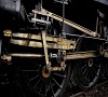
The push pull apparatus is based on the alan Gibson white metal castings. A new wrapper has been formed, and some pipework added (control pipe yet to be added). As shown here, the control rod between the two parts will sit vertically...
20200531_194846.jpg
The ejector uses two parts of the Craftsman white metal lump, alongside several bits of rod, tube and fuse wire. A spare Rumney models brake link is used for the diamond shaped front. All in all rather pleasing.
20200509_112320.jpg
20200509_113629.jpg
20200531_112442.jpg
20200531_141314.jpg
The following photo is with it still in separate sub sections, I am aware the pipework each side if the ejector isn't in a straight line. There is also 1 more pipe still to add.
20200531_142114.jpg
The handbrake is a spare Dave Bradwell casting, designed to control a tender water scoop. This has a new bit of brass for its base with some rivets embossed. The front cylinder cover has been added and raised. The sides need tidying up, and more rivets adding (though I currently plan to do this with archers after priming). I haven't specifically taken photos of either of these bits, but the covers can be seen in corners of others.
Returning to the push pull equipment, the lower cylinder is offset out from the outside of the splashers on 58066. This doesn't necessarily seem to be the location on all 1Ps, some manage to line up with the splasher - and it doesn't appear to be as clear cut as a 1833/2028 difference. Having got the location looking right in relation to the splasher, the control rod will be nothing like vertical... so back to the drawings to assess what is out.
This determined that the main splashers should measure 22.66mm, and 26.66mm over the coupling rod boss clearance section. I had used the Craftsman castings as is, lining them up with the inside of the footplate. They are 2 of the 3 castings I have used as supplied (the third being the dome) so I should have known something may have been amiss at the time. These measure 26.7mm over main and 30mm over rod bosses.
I recall wondering at the time whether the white metal castings may be too thick, but taking a look at the rod boss section decided it looked like a reasonable chunk of hard work to do anything else, so used them as is, and moved on. Note to self, this has come back to bite!
20200531_142229.jpg
20200531_142304.jpg
Options I'll be mulling over this week:
1. Leave the splashers as they are, move the lower push-pull cylinder in line with control valve. Wrong for this 1P, though others did have that setup. Obviously the quickest route forward...
edit - 1.5! remove some from rear of splashers, and see if they will sit inboard without clouting the wheels...
2. Assess Brassmasters 4F splashers I have lurking. I used the 3F ones with success, they look the part, and all being 5'3" wheels should nominally be the same - yet 3Fs and 4Fs don't have the rod boss section, so presumably the footplate is higher on those so as not to need that section, and so the splashers will be smaller. If they are ok, these could potentially reuse part of the castings for that front section.
3. As 2, but with scratch built main splashers if the Brassmasters ones aren't quite right. Beading could be fun...
4. As 3, but etched - which would make forming a uniform curve easier, and make the beading easier.
Any replacement is likely to still be marginally over scale, but should be close enough to allow the location of the lower cylinder to look right, at the same time as the control rod being vertical.
All jolly good fun...
You do not have the required permissions to view the files attached to this post.