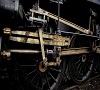
Hi All. Some of you may be aware I have been locked into mortal combat with a Brassmaster 4F, for which it was getting the better of me. I've not touched it since moving into my new workshop, railway room, shed a couple of years ago. In an attempt to clear my back log of unfinished stock and the need of more motive power for my layout, also fed up with the thing just sitting there mocking me, I vowed this would be next to do. So on Christmas Day I laid the parts in front of me in an attempt to fathom where I had left off and how to precede. First port of call was how the body and chassis come together. The chassis goes into the body/footplate front first and locating the front end of the chassis under a piece of brass plate sticking out from behind the rear of the buffer beam and then the rear of the chassis then slides into the rest of the footplate and secured by a screw. The problem I found is where the frames come through the footplate to form the sides of the smoke box, the rivet and inspection plate covers would catch on the edge of the footplate. So you would have to enlarge the slot in the footplate to allow the frames and this detail to come through. This would leave an unsightly gap in the foot plate. The two relief valves which protrude from the frames would also have to be removable. In an thread I did on this forum sometime ago, someone mentioned what they did was to remove the front part of the frames where they protruded from the footplate and permanently fixed them to the footplate itself, which sorted this problem out. For me this was too late but when I was looking back through the instructions there was mention about dummy front frames for OO and EM. So I rooted through my scrap etch parts box and found the two front frames. First off I removed all the raised detail from the front of the chassis and fitted it to the body. I then added all the raised details to the dummy frame pieces and tact solder them in place on the footplate butted up hard against the frames, removed the chassis and finished the solder seems on the dummy frames bits. Apart from the chassis will now fit in the body much easier the relief valves can be permanently fixed in place. Boyd up with this success I moved onto fitting the inside motion in the frames. This was a right sod to do and I really happy seeing all the paint being scraped off as one tried to squeeze in the motion support bracket into place. After much swearing and cursing all the little bits and bobs were in place with only one joint braking in the process. I managed to fix it and then fitted the wheels. To my amazement as I turned the wheels all the motion started to move as well, great I thought now to fit the motor, pick ups and decoder etc, so I placed the chassis down on my cutting map and dug all the electrical bits out of the box. As I picked up the chassis again to see where I can place the pick up I noticed where the chassis was sitting a small lump of brass. On closer inspection it was a captive nut and screw which held the sleeve that connects the motion to the main driving axle. I was thinking of something that rhymed with clanging bell. This nut and screw sits between the two sets cams and big ends on the centre axle. If I could get a soldering iron in this area I'm sure the heat would melt any surrounding solder and lock the entire motion up solid. So the nut and screw will have to remain off until there is a need to remove the wheels so I can remove the sleeve to reinsert it. Although the inside motion did work I'm not too fussed about not having it working as I don't know if this would cause any drag on the loco when running. I have another two of these 4F's to make anyway so I more chances of making it work anyway. Right back to fitting the pick ups and motor, hopefully without any more bits dropping off.
Dave
Brassmaster 4F The journey
-
Serjt-Dave
- Posts: 643
- Joined: Tue Oct 02, 2012 3:31 pm
Brassmaster 4F The journey
You do not have the required permissions to view the files attached to this post.
-
nberrington
- Posts: 578
- Joined: Thu Dec 04, 2008 2:15 pm
Re: Brassmaster 4F The journey
I love the inside motion. Neat work Dave.
-
Serjt-Dave
- Posts: 643
- Joined: Tue Oct 02, 2012 3:31 pm
Re: Brassmaster 4F The journey
A loco is born. Chassis is now all wired up, motor and decoder fitted and tested. As always to my surprise it runs fairly well. It has to be bedded in and lubed up but I won't do the until it's repainted and the final bits are added, like the remainder of the brake gear and sand pipes. But I can now turn my attention to the body.
Dave
Dave
You do not have the required permissions to view the files attached to this post.
-
Serjt-Dave
- Posts: 643
- Joined: Tue Oct 02, 2012 3:31 pm
Re: Brassmaster 4F The journey
Just when you thought it was safe to continue with building this 4f something comes along and bites ya! I was quite happy the the performance of the chassis and all seemed well. I was weighting up the body and giving it a test run when it started to judder and then stop. As I picked it up off the track the firebox seemed a bit warm in fact very warm, took the body off and the motor was very hot. I waited for it to cool right down and retested it but without the body on it tried to move made a strange noise and stopped. Took the rods off the front and middle drivers rotated freely so I removed the motor and found the rear divers had stuck. I removed the rear axle/gearbox and one of the hornblock was jammed on to the axle. Removing the hornblock to some effort and in the process I had to remove the main gear cog off the axle as well. What caused the hornblock to attach itself to the axle I have no idea, however the hornblock face plate had become damage but I don't know if that was caused during running or me trying to remove it off of the axle. I cleaned up the hornblock and replaced the face plate, clean up and reattached the main gear cog and reassembled the rear drivers back in the frames. Retested the chassis with the body on and all seems okay {for now?}. Looking at the image of the underside of the chassis I've noticed the front lefthand side driver is looking a bit wonky, so will have to take a look at that.
Moving onto the body I decide to remove some of the grab rails as they have become bent up through handling and will replace in due cause. Next I decide to tackle the sand box filler caps. As you can see from the second image the castings supplied are just totally wrong. After much fettling I've ended up with something half decent {ish}. The holes in the foot plate are now too big for the middle and rear sandboxes and the rear ones don't line up with the cut out in the firebox. Now to tackle the handrails. The pre-drilled holes in the boiler are too high and so needed to be filled this is most apparent on the smoke box door as one of the holes cuts into the door hinge. To form the handrail supports the kit supplies steel split pins. I'm not going to go down that road, so opted to making the supports out of copper wire. Looking at Brassmasters test build of the 4f it looks like they used either copper wire or copper split pins, so why supply bloody steel ones which you can't bend. LOL. The thinner piece of the handrail needed a stopper at the end. I did this by using a single strand of copper wire wrapped around the end of the handrail. I was quite pleased with end result {no pun intended}. To fit the reversing leaver you needed to cut a slot in the end of the firebox depending which side you have it. Not the easiest of tasks to do but I got there in the end. I dug out the slot to about 8mm deep into the firebox but the reversing leaver is somewhat longer so I decide to trim the leaver. carefully measuring where I need to cut I chopped off the rear of the leaver. Went to fit it and it was a bit too short. Looking at the cut off part of the leaver I could clearly see where I had marked it so it looks like I mistook a scratch as my mark. Bugger!
Moving onto the body I decide to remove some of the grab rails as they have become bent up through handling and will replace in due cause. Next I decide to tackle the sand box filler caps. As you can see from the second image the castings supplied are just totally wrong. After much fettling I've ended up with something half decent {ish}. The holes in the foot plate are now too big for the middle and rear sandboxes and the rear ones don't line up with the cut out in the firebox. Now to tackle the handrails. The pre-drilled holes in the boiler are too high and so needed to be filled this is most apparent on the smoke box door as one of the holes cuts into the door hinge. To form the handrail supports the kit supplies steel split pins. I'm not going to go down that road, so opted to making the supports out of copper wire. Looking at Brassmasters test build of the 4f it looks like they used either copper wire or copper split pins, so why supply bloody steel ones which you can't bend. LOL. The thinner piece of the handrail needed a stopper at the end. I did this by using a single strand of copper wire wrapped around the end of the handrail. I was quite pleased with end result {no pun intended}. To fit the reversing leaver you needed to cut a slot in the end of the firebox depending which side you have it. Not the easiest of tasks to do but I got there in the end. I dug out the slot to about 8mm deep into the firebox but the reversing leaver is somewhat longer so I decide to trim the leaver. carefully measuring where I need to cut I chopped off the rear of the leaver. Went to fit it and it was a bit too short. Looking at the cut off part of the leaver I could clearly see where I had marked it so it looks like I mistook a scratch as my mark. Bugger!
You do not have the required permissions to view the files attached to this post.
Last edited by Serjt-Dave on Tue Jan 21, 2020 8:28 am, edited 1 time in total.
-
Horsetan

- Posts: 1380
- Joined: Tue Jul 29, 2008 9:24 am
Re: Brassmaster 4F The journey
Serjt-Dave wrote:... Not the easiest of tusks...
At least the model isn't the elephant in the room anymore
That would be an ecumenical matter.
-
Serjt-Dave
- Posts: 643
- Joined: Tue Oct 02, 2012 3:31 pm
Re: Brassmaster 4F The journey
Thank you Horsetan for pointing out my spelling mistake {which has now been corrected}. In my defense it was written whilst suffering the effects of man flu. LOL. But thank you for reading all the way through my dribbling's.
Dave
Dave
-
Serjt-Dave
- Posts: 643
- Joined: Tue Oct 02, 2012 3:31 pm
Re: Brassmaster 4F The journey
Here's the next installment, not much to show as my bout of mega man flu knocked me somewhat. Anyway finished the ejector which I'm quite pleased with. Only used three bits from the original casting. One thing I did cock-up on, I put the lefthand side handrail on the rightside {but the wrong side if you get what I mean} and only noticed when marking out for the ejector. All sorted now. Added a few other bits and fast running out of bits from the kit to add. Then I can move onto making the bits the kit didn't supply.
I was going to use the lubricators that were supplied with the kit but they are so out of square I've ordered some brass replacements. I've got to use the air relief valves supplied as I don't know of any decent replacements. I'll hack them about to see if I can make anything half decent out of them. The builds end is coming into sight.
Dave
You do not have the required permissions to view the files attached to this post.
-
PeteT

- Posts: 472
- Joined: Tue Jan 11, 2011 9:53 pm
Re: Brassmaster 4F The journey
Serjt-Dave wrote: finished the ejector which I'm quite pleased with
So you should be Dave - that looks brilliant! I've been contemplating how to improve the Alan Gibson ejector casting for use on my 1P, so any advice you can give on how you got there would be much appreciated. How many individual pieces does it consist of?!
Edited to add that the drawing in Midland Record 4 is especially useful to help know what to aim for.
Cheers,
Pete
-
Serjt-Dave
- Posts: 643
- Joined: Tue Oct 02, 2012 3:31 pm
Re: Brassmaster 4F The journey
Thanks Peter. I spent most of the morning writing a detailed report on how I made the ejector, had almost finished when I had to pop out. When I got back the computer must of had a blip and I lost it all. So I ain't got the strength to start it again. LOL. Here's the short version. The Part count comes to 28 bits, that does include all the little bits of wire that make up bolt heads but doesn't include handrails. If your modifying a Gibson on I take it that will be in lost wax brass which will be a pig to drill holes into. If you want one of my spare white metal castings let me know. I do have them in left and right handed versions. I've attached an image showing some of the quality castings supplied with the kit.
All Best.
Dave
All Best.
Dave
You do not have the required permissions to view the files attached to this post.
-
PeteT
- Posts: 472
- Joined: Tue Jan 11, 2011 9:53 pm
Re: Brassmaster 4F The journey
Gah, thanks for spending the time!
Yes the Gibson casting is lost wax. I do have the original provided by craftsman, in white metal, so while I discounted it as poor it may have the right blocks within it to work with. I'm away this weekend but will have a check when I'm home - I may be in touch if the casting is worse than the ones you have, so thanks for the offer - much appreciated whether or not I take you up on it.
As I understand it the Brassmasters kit is supplied with SE Finecast castings. I presume there is no link to the Craftsman ones. Most of the castings supplied with the 1P were terrible.
-
Serjt-Dave
- Posts: 643
- Joined: Tue Oct 02, 2012 3:31 pm
Re: Brassmaster 4F The journey
Hi Peter, yeah sorry about that. It was a cracker of a article as well. It even mentioned me dropping the top part of the ejector on the floor and running it over with my chair. LOL.
Yes your right the casting are from SE Finecast and from the last century. It really let the kit down. Especially when you see their castings they use on their other kits, so why use very poor and old WM castings on a new kit?
No worries let me know if you need it. I'll probably be on the scrounge for some of the bits you've made for the 1p.
All Best
Dave
-
PeteT
- Posts: 472
- Joined: Tue Jan 11, 2011 9:53 pm
Re: Brassmaster 4F The journey
Hi Dave,
Thanks for the photo - the Craftsman ejector looks to be the same casting. It is a bit of a bigger block than the Gibson brass one. The midland record drawing is actually a slightly difference design to the 1P - I have seen as the drawing on 4Fs. The Bachmann rendition on the 3F isn't bad actually, so while I don't like modelling models it does help work out what is going on in some photos (ie I can look at it from all angles!). It may also help me clarify a few dimensions.
All good fun...
Edited to add that this reminded me to dig out Steve Hall's 3F article (in MRJ 151) - which has a drawing for the ejector he assembled for that - which was around a block of brass. I guess the brass route does allow it to all be soldered together.
-
PeteT
- Posts: 472
- Joined: Tue Jan 11, 2011 9:53 pm
Re: Brassmaster 4F The journey
This may not be the best place for this, but while I've started I'll finish (as they say).
The Alan Gibson casting is an ok starting point for the ejector fitted to some 1Ps (or all & later swapped?). This photo is even on Ilkley shed, but in LMS days (loco 1413):
Then we have the Craftsman casting, & the ejector I need (on 58066):
Unfortunately the latter is quite fuzzy, but shows enough of the type it is to compare it with 3Fs - just the attachment & run of the pull rod which is arranged differently. I'll come back to this on my topic when I pluck up the courage to make it! I have bunker & tank detailing to attend to first...
You do not have the required permissions to view the files attached to this post.
-
Serjt-Dave
- Posts: 643
- Joined: Tue Oct 02, 2012 3:31 pm
Re: Brassmaster 4F The journey
Not a great choice is it. LOL. As you say with the brass on at least you can solder everything but it's a bugger to drill, wheres the white metal is easier to modify but you have to glue or very carefully low melt solder. You pays ya money and takes ya choice. Good luck.
Dave
Dave
-
jim s-w

- Posts: 2189
- Joined: Wed Jul 30, 2008 5:56 pm
Re: Brassmaster 4F The journey
The London road models one might be better than these 2
Cheers
Jim
Cheers
Jim
-
Serjt-Dave
- Posts: 643
- Joined: Tue Oct 02, 2012 3:31 pm
Re: Brassmaster 4F The journey
Thanks Jim I'll check. In the back of my mind though aren't LRM the ex-MayGib range? So they might be the same castings as the Gibson ones. I have a LRM Jinty and 3f so will check their ones.
Dave
Dave
-
PeteT
- Posts: 472
- Joined: Tue Jan 11, 2011 9:53 pm
Re: Brassmaster 4F The journey
The LRM one for the LMS 2P 0-4-4 is definitely streets ahead (but left hand drive). I checked my mothballed LRM 3F box the other day & that one has gone AWOL. If it is a mirror of the 3F it would be the best starting point though.
-
Serjt-Dave
- Posts: 643
- Joined: Tue Oct 02, 2012 3:31 pm
Re: Brassmaster 4F The journey
This is a image of the LRM ejector. It looks like a nice casting with little indentations for the extra pipework etc especially where the handrail locates but this is different to the 4f version.
Dave
Dave
You do not have the required permissions to view the files attached to this post.
-
Serjt-Dave
- Posts: 643
- Joined: Tue Oct 02, 2012 3:31 pm
Re: Brassmaster 4F The journey
After my little break from the 4f I decided to tackle the train system control panel or backhead to you and me. As you can see from the image the original casting is nothing like what it should be, I don't think it's even for a 4f. As there was very little in the way of any of the cast details on the main backhead I removed all except the firebox doors, the regulator hole and the two glass thingies. All the replacement parts were made up from copper and brass wire, washers, scraps and an etch of hand wheels. It's a bit cramped mainly for the backhead being undersized and some of the items I made being slightly oversized but I'm quite pleased with the end result.
Keep Safe and Keep Modelling
Dave
Keep Safe and Keep Modelling
Dave
You do not have the required permissions to view the files attached to this post.
-
Noel

- Posts: 1981
- Joined: Wed Jun 23, 2010 1:04 pm
Re: Brassmaster 4F The journey
Serjt-Dave wrote:the two glass thingies
Gauge glasses, behind protectors, for showing boiler water level. Incidentally, it looks as though the original casting was intended for a left hand drive loco, whereas your very impressive construction is for a right hand drive loco.
Regards
Noel
Noel
-
Serjt-Dave
- Posts: 643
- Joined: Tue Oct 02, 2012 3:31 pm
Re: Brassmaster 4F The journey
Thanks Noel. I knew what they were for but couldn't remember what they were called. Your correct the casting was for a left handed loco {whatever loco it was made for}. The S&D had both left and right handed 4f's, the two I'm doing are 44559 and 44560 which were both right handed. The firebox opening mechanism had to be removed and changed over as well.
Dave
Dave
-
Serjt-Dave
- Posts: 643
- Joined: Tue Oct 02, 2012 3:31 pm
Re: Brassmaster 4F The journey
A bit more progress. The last major hurdle {I hope!} Fitted the lubricators. As with most of the kits casting they had to be replaced. I opted for Markit's turned brass ones but even they had to be modified. The lip around the top of the lubricator was only represented just down the sides, so I soldered some bent wire to the front and back. I then put lengths of tubing through the ports. This helped by looking like there were nut fittings where the feeds came through the ports and also reduced the size of the wire to represent the copper feeds. I also reduced the handle thingy sticking out the front of the lubricator and made it look a bit better as well. Brassmasters kindly provide parts to make the lubricators work, but don't provide instructions on how to. I opted not to have mine working {wimp I hear you cry} I did add all the bits they provided. However they didn't included the operating rods from the lubricators to the motion support bracket. I thought that could be quite crucial in making them work but hey what do I know. Actually fitting the lubricators to the loco was the next challenge. In real life they are bolted to the top of the frames but in model form we need to be able to remove body so another method is required. I made up a couple of brass brackets which I soldered to the bottom of the lubricators butted them hard up against the frames but attached to the foot plate. I would have preferred to solder the bracket to the foot plate rather than glue it but I didn't want to risk using a iron in such a confined area and with a resin boiler and white metal casting etc. The next one {god not another one? No another two} I will install them before the boiler and other vulnerable are fitted.
Other than some cab castings I've used up all the parts provided in the kit. Now I've got to add all the the bits the kit didn't. Like a fall plate!
Keep Safe
Other than some cab castings I've used up all the parts provided in the kit. Now I've got to add all the the bits the kit didn't. Like a fall plate!
Keep Safe
You do not have the required permissions to view the files attached to this post.
-
Wizard of the Moor

- Posts: 191
- Joined: Mon Jul 21, 2008 9:02 pm
Re: Brassmaster 4F The journey
Those lubricators look the business, Dave. Really nice work 
-
Julian Roberts

- Posts: 1393
- Joined: Sat Jan 09, 2010 11:33 pm
Re: Brassmaster 4F The journey
Lovely stuff Dave. Wonder what your drugs are....looks like they do the business. viewtopic.php?f=133&t=6708&p=73906#p73906
Lubricators and ejectors, all the same stuff but different to my Compound. My drugs are just tea and coffee...so far! Wish I'd thought of getting Markits lubricators. What size copper wire and tubing did you use?
Lubricators and ejectors, all the same stuff but different to my Compound. My drugs are just tea and coffee...so far! Wish I'd thought of getting Markits lubricators. What size copper wire and tubing did you use?
-
PeteT
- Posts: 472
- Joined: Tue Jan 11, 2011 9:53 pm
Re: Brassmaster 4F The journey
Thanks for sharing Dave. I have some of the Markits lubricators in stock and likewise think they are a good starting point - hopefully I'll make as good a go of finishing them as you have!
Who is online
Users browsing this forum: ClaudeBot and 0 guests