Turning Six Splashers for 3'6" wheels that sit 1.1mm high above the footplate
This is a very simple job to turn. They need to be cut on both sides to go over the wheel on one side and recessed for the beading on the other, I also need 6. So will need to do it two units.
Starting with a block of brass 3/4inch diameter in the 3 Jaw chuck. First cut using a slightly rounded cutter is to reduce the end so that it will fit in a 1/4 inch collet.
With one end cut to 1/4 inch and fitted in the collet the other end needs to be done as well to make two units
The outer edge has also turned down to 16.5mm which is slightly more than it needs to be.
Now I need to cut out to make the internal part of the splasher
This is done with a 3mm boring cutter I start at the 1/4 inch spigot push into the metal to be removed about 1/2mm wind out the cross slide to a internal measurement of the splasher at 15mm and draw the cutter out again. The wheels over the flange measure 14.6mm
Repeating this movement over and over to a depth of about 4mm.
Then turn the unit round and repeat. Once both ends are done the outer wall can be thinned down to about .4mm thick and the edge cleaned up and reduce the depth to 3mm then polish with fine emery paper.
Then unit can now be split in two.
Now face the outer section of the splasher to a depth of 4mm.
A recess has now been cut in the face to a depth of .5mm using the 3mm boring cutter again
I have not bothered Polishing up the centre of the face as it will end up in the scrap.
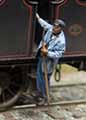
Now the two complete splashers are done I have slipped in a 3'7'' coach wheel tyre in to make sure it fits without touching.
I can get 4 splashers out of each one. So mounted in the watchmakers lathe which has a milling attachment with a slitting disc in.
Using the indexer on the other side of the headstock I can hold the splasher unit fast and slice off the 4 quarter splashers
Leaving the last few thou to be cut by hand so I do not shoot the splasher across the table.
The six splashers are now all done. I have sliced them off 1.5mm deep so they will allow a little leeway for the compensation but could be filed down a bit later if required.
Tips and tricks in machine tool practice
-
Jeremy Suter
- Posts: 360
- Joined: Tue Apr 14, 2009 6:56 pm
Re: Tips and tricks in machine tool practice
You do not have the required permissions to view the files attached to this post.
Tips and tricks in machine tool practice viewtopic.php?f=132&t=6350
-
Terry Bendall
- Forum Team
- Posts: 2427
- Joined: Sun Jul 27, 2008 7:46 am
Re: Tips and tricks in machine tool practice
A neat idea Jeremy. The work in the lathe is fairly straightforward but for those without the facility to index and cut the segments from the bar it would be necessary to hold the spigot in a vice and use a saw to cut them off. I would probably use a piercing say to do that job.
Terry Bendall
Terry Bendall
-
Daddyman
- Posts: 745
- Joined: Sat Jun 03, 2017 1:09 pm
Re: Tips and tricks in machine tool practice
Jeremy Suter wrote:The six splashers are now all done. I have sliced them off 1.5mm deep so they will allow a little leeway for the compensation but could be filed down a bit later if required.
The splashers will have a base too - 5 thou I think - which gives me a little more clearance. But I wonder how people calculate splasher height in P4? Presumably true-scale splashers are not possible and I need to add a bit of leeway for the wheels moving under springing?
-
grovenor-2685

- Forum Team
- Posts: 3923
- Joined: Sun Jun 29, 2008 8:02 pm
Re: Tips and tricks in machine tool practice
As did the prototype.Daddyman wrote:and I need to add a bit of leeway for the wheels moving under springing?
-
John Bateson

- Posts: 809
- Joined: Wed Jul 02, 2008 6:39 pm
Re: Tips and tricks in machine tool practice
Here is what I do.
The frame shows an axle box (Markits) located on the second, driving axle. This is centered on the wheel centre height. The front wheel shows the official P4 and EM flange measurements to be added to the main wheel radius.
I allow the cut out in the frame to be 2" or 0.67mm above the top of the Markits axle box so that the wheel is limited in upwards movement. Some designers use 1.5" or 0.5 mm.
To this must be added the thickness of the splasher, probably 0.3 mm to give the top of the splasher.
John
PS for axle box read hornblock although this is a little inaccurate as a true description.
You do not have the required permissions to view the files attached to this post.
Slaving away still on GCR stuff ...
-
Daddyman
- Posts: 745
- Joined: Sat Jun 03, 2017 1:09 pm
Re: Tips and tricks in machine tool practice
John Bateson wrote:Here is what I do.
010 Class 8H V0.2 Splashers Spacing.PNG
The frame shows an axle box (Markits) located on the second, driving axle. This is centered on the wheel centre height. The front wheel shows the official P4 and EM flange measurements to be added to the main wheel radius.
I allow the cut out in the frame to be 2" or 0.67mm above the top of the Markits axle box so that the wheel is limited in upwards movement. Some designers use 1.5" or 0.5 mm.
To this must be added the thickness of the splasher, probably 0.3 mm to give the top of the splasher.
John
PS for axle box read hornblock although this is a little inaccurate as a true description.
Thank you, John. I'll take some time to get my head round that.
-
Jeremy Suter
- Posts: 360
- Joined: Tue Apr 14, 2009 6:56 pm
Re: Tips and tricks in machine tool practice
Parting off a chimney in the centre so there is no locating spigot and fitting a casting plug
Staring with a chimney I have shown how to make earlier in this thread.
This is a 7mm scale Stannier 262t Chimney and will be going for casting.
The inside has been nearly finished with a tapered hole about 7/8th the way down.
I now have to remove this spigot which means I have to drill it out but the hole needs to be a taper.
Mounted in the watchmakers lathe with the lead screw angled at 2o to taper the inside wall.
The cutter is like a long knife. It started as 3mm square ground down to a triangle about 2mm thick on the rear face and tapering to the point. The cutting edge is the approximately 2mm shinny bit at the tip you can see in the picture. It looks parallel to the outer part of the chimney but is only cutting with the point on the way in and the shine on the way out.
To part the chimney from the base the cutter is run in along the inner wall cutting it to the correct thickness required as far as it goes plus and a little bit more then screw in with the cross slide about 1/2mm to cut the bottom. Then do it again until I reach the depth required.
You can see the line of cut on the rear face inside.
After several goes I need to make sure I don't cut clean off as the spinning the chimney loosely on the cutter will not do it any good.
After measuring the length of cutter against the chimney give it a gentle push and it should give.
There will be a slight push in the metal as the cutter wants to break through.
The rough edge can be cleaned with a fine grade file.
The waist
The Casting plug will be made of Tufnol rod. Its not a very nice product to turn although it does turn very well, the smell is a bit obnoxious and not very good for you health either. So I usually do it with a vacuum cleaner sucking up the chips. I say chips but its actually a very fine dust and seems to get everywhere.
A taper will be turned on the rod at 2o to match the internal angle of the chimney.
The tool post lead screw angle has been set.
Using cuts of about 1mm to get the rod diameter to fit the chimney.
Chimney slotted on and the plug can be parted off with a piercing saw.
Finished chimney's and pugs with the rest of the parts for that job.
You do not have the required permissions to view the files attached to this post.
Tips and tricks in machine tool practice viewtopic.php?f=132&t=6350
-
Terry Bendall
- Forum Team
- Posts: 2427
- Joined: Sun Jul 27, 2008 7:46 am
Re: Tips and tricks in machine tool practice
More interesting stuff Jeremy. Please excuse a small correction to terminology
The lead screw is the threaded bar that is found on an engineer's lathe along the front of the bed and is used to move the carriage along the bed. Some lathes will have a hand wheel on the right hand end to achive this and in most casaes the threaded bar is connected by a system of gears to give a power feed and to allow a screw thead to be cut using the lathe.
What Jeremy has shown is how to set the top slide at an angle to produce a taper. Not all lathes have this facility but it is the only easy way to turn a taper on a small lathe.
Turning Tufnol will also blunt the tool quite quickly. WEaring face mask to FFP3 grade is also a good idea.
Terry Bendall
Jeremy Suter wrote:Mounted in the watchmakers lathe with the lead screw angled at 2o to taper the inside wall.
The lead screw is the threaded bar that is found on an engineer's lathe along the front of the bed and is used to move the carriage along the bed. Some lathes will have a hand wheel on the right hand end to achive this and in most casaes the threaded bar is connected by a system of gears to give a power feed and to allow a screw thead to be cut using the lathe.
What Jeremy has shown is how to set the top slide at an angle to produce a taper. Not all lathes have this facility but it is the only easy way to turn a taper on a small lathe.
Jeremy Suter wrote: The Casting plug will be made of Tufnol rod. Its not a very nice product to turn although it does turn very well, the smell is a bit obnoxious and not very good for you health either. So I usually do it with a vacuum cleaner sucking up the chips.
Turning Tufnol will also blunt the tool quite quickly. WEaring face mask to FFP3 grade is also a good idea.
Terry Bendall
-
Jeremy Suter
- Posts: 360
- Joined: Tue Apr 14, 2009 6:56 pm
Re: Tips and tricks in machine tool practice
Turning a Safety valve which is not round.
I have been given an Arthur Kimber kit for the Tennent 240. The castings supplied both in white metal and lost wax brass are very poor, especially the dome and safety valve . The dome is tapered rather than parallel, and the safety valve is too small and twisted.
The only option is to remake them.
Starting with the fly cut to go round the boiler. The brass bar is mounted on the vertical slide, centre level found and the fly cutter is set to the radius of my boiler 8.75mm. The bar already had a small hole in the end but not deep left from a previous job.
Once the fly cut is done a hole needs to be put in the base to mount the safety valve ready for doing the top. I need a 2mm hole rather than a 1/8inch which is my usual, we will see why later.
One thing I have not said earlier in these post is that the three jaw chuck or self centering chuck spins off centre and why we should use collets for certain jobs. This chuck spins .03 mm off centre on the no3 jaw.
If I set the curve of the bar in line with this jaw the finished item is not off set to one side on the model and will correct it self as we turn down the side.
The basic shape needs to be put in before parting off.
With basic shape done and spigot added this is an 1/8 inch rod turned to fit the 2mm hole in the base. Just need to part off from the bar.
Once parted off I have fitted it in the flare Jig which I have shown in earlier posts. This is why I use a 1/8 inch rod as a standard base.
Now rotating the flare jig by 90o to change the point of cut as the ball cutter isn't actually a ball but a wide ellipse. This changes the angle of cut to a softer curve.
Base milled.
Now centred in the watchmakers lathe.
A half round file is used to blend in the two curves. Once done is finished with fine emery papers.
Now the top needs to be put in. Using right handed cutter to cut under the lip and the sides it has a 1.5mm radius changing to a 5mm radius on the left hand side. This is a right hand cutter so I start at the left hand end and work backwards to the top of the safety valve. The curve needs to be tighter and have some 1mm round files for this job although they are getting shorter and shorter.
A pointed cutter to do the top.
I use a round file to tighten the curve over the top of the boiler. and finish with fine emery papers
This gives us a round safety valve. The top still needs to be hollowed out. I did the dome first but already shown how to do them
The next job is to remove the sides of the safety valve.
You do not have the required permissions to view the files attached to this post.
Tips and tricks in machine tool practice viewtopic.php?f=132&t=6350
-
Jeremy Suter
- Posts: 360
- Joined: Tue Apr 14, 2009 6:56 pm
Re: Tips and tricks in machine tool practice
With the dome done.
The safety valve needs finishing by taking off the sides and making it oval shape.
To do this in the lathe I need to off set the safety valve far enough away to only cut the the side and produce a very shallow curve.
Off setting the safety valve by 5cm will give a very shallow curve.
The block has been drilled to fit the safety valve 5cm from centre and a piece of bar turned to 17.75mm drilled and milled out to go over the bar so as to keep the safety valve square on to the centre and a tightening screw to hold it in place.
Mounted in the chuck, the same cutter I used to form the shape is now fitted to the tool post and starting just under the lip.
I could spin the chuck to cut but it will make this lathe shake a bit. So I just flick the safety valve over the cutter by hand moving the toll in slightly between each cut.
After doing the first side making a note of where I start and finish on the cross slide and top slide dials. so I can turn the safety valve round and do the other side.
With both sides done its back in the block. The top slide angle is changed to do the lower edge and repeat what we did before.
With the lower sides done the top is next step for the same treatment but with a pointed cutter. once that is done the rim can be taken back.
Now mounted in a 5mm offset block I have rounded the corners in the same manor as the sides.
Now mounted in the Watchmakers lathe I need to blend in all the angles with files and emery papers.
The shape is all done.
The inside now needs to be drilled out and am putting a centre drill in to put a dimple in the centre for later.
With a starting point I can mount the safety valve back on the block I used earlier and mount for milling This could be done in the lathe.
I prefer to use the milling machine.
Starting in the centre and zeroing the table dials I can work out how far I need to move the table to cut a hole in the top 4.5mm long by 2.5mm wide which is why I needed a 2mm spigot so that the sides would be sold for this part.
Top is now machined out 2.5mm deep. The dimple from the centre drill can be just seen on the bottom.
Back into the watch makers lathe I will put a 1mm hole down the centre this finishes this part of the safety valve.
The final stage is to make the Ramsbottom valves that can be seen inside.
I first cut the arm out in 30 thou plasticard 3 times bigger than needed and mount on a board ready to be pantograph milled.
Using a 1.5mm cutter so that means I have a 4.5mm runner to go round the pattern and cutting it out in 15 thou nickel silver.
The long base is 1mm wide to slot into the 1mm hole we made.
Now I need 2 valves which are turned out of 1.5mm rod in the watchmakers lathe two cuts and 2.75mm deep and part off.
A slot cut in the top to fit to the arm and a spring made from .3mm wire wound round a file and then all soldered together.
All fitted together just need two whistles to fit in the cam to finish.
The best thing about this kit is that the boiler and cab can be removed from the footplate and the smoke box can be removed from both. There are some twist lungs to hold and tighten the parts together after painting.
You do not have the required permissions to view the files attached to this post.
Last edited by Jeremy Suter on Fri Dec 23, 2022 9:36 am, edited 1 time in total.
Tips and tricks in machine tool practice viewtopic.php?f=132&t=6350
-
andrewnummelin
- Posts: 374
- Joined: Mon Jul 21, 2008 9:43 am
-
Suffolk Dave
- Posts: 74
- Joined: Mon Nov 15, 2021 4:48 pm
Re: Tips and tricks in machine tool practice
Elegant and beautiful!
Check out my modelling activity here: https://www.instagram.com/4mm_dave/
-
Winander

- Posts: 861
- Joined: Thu Mar 20, 2014 12:19 pm
Re: Tips and tricks in machine tool practice
Jeremy Suter wrote:There are some twist lungs to hold and tighten the parts together after painting
Another excellent and useful thread. Can I ask for more about the above - I assume there's a typo (lugs?), but what do they look like and how do they work?
thanks
-
Daddyman
- Posts: 745
- Joined: Sat Jun 03, 2017 1:09 pm
Re: Tips and tricks in machine tool practice
Very interesting, Jeremy. Looks more like a Tennant now - not that that's a good thing...
Looks as if, like me, you also replaced the oversize beading on the rear cab edge?
Looks as if, like me, you also replaced the oversize beading on the rear cab edge?
-
Jol Wilkinson

- Posts: 1116
- Joined: Mon Jul 21, 2008 7:39 pm
Re: Tips and tricks in machine tool practice
I have a s/h Tennant kit on the way from foreign parts, and am a little dismayed to learn that the boiler fittings aren't very good. I'll have to see what I can find elsewhere (LRM?) as getting Jeremy to make me set might be beyond my budget!
-
Terry Bendall
- Forum Team
- Posts: 2427
- Joined: Sun Jul 27, 2008 7:46 am
Re: Tips and tricks in machine tool practice
Very interesting Jeremy. The off set mounting of the safety valve is an idea that i have not seen before. Thanks for the information.
Terry Bendall
Terry Bendall
-
Jeremy Suter
- Posts: 360
- Joined: Tue Apr 14, 2009 6:56 pm
Re: Tips and tricks in machine tool practice
Winander wrote:Jeremy Suter wrote:There are some twist lungs to hold and tighten the parts together after painting
Another excellent and useful thread. Can I ask for more about the above - I assume there's a typo (lugs?), but what do they look like and how do they work?
thanks
Hi Richard
Yes they are lugs I do like it when a model can be taken apart into smaller pieces for painting does make it easier than masking as well as lining it.
Hi David.
The beading was replaced, like you I thought it too fat so replaced it with copper wire and filed flat.
The lugs fit through the slots in the footplate and should be twisted to hold fast after painting.
You do not have the required permissions to view the files attached to this post.
Tips and tricks in machine tool practice viewtopic.php?f=132&t=6350
-
Daddyman
- Posts: 745
- Joined: Sat Jun 03, 2017 1:09 pm
Re: Tips and tricks in machine tool practice
I can't see from the photos what the smokebox door was like in your kit, Jeremy, but mine was far too dished - the real Tennants had a very flat door.
Another thing is the coal rails: the proportions of those supplied look wrong (too much rail and not enough gap). I substituted some spare Bradwell ones, but the originals can be improved by running a mouse-tail file between the rails to make them look more half round - but you may have done that already.
Season's greetings!
David.
-
Edward45
- Posts: 46
- Joined: Mon Jun 06, 2016 2:53 pm
Re: Tips and tricks in machine tool practice
Just on or two things. This was one of Arthur's earlier kits and since that time a better safety valve has been produced, I believe this is also the case with the smokebox door.. Castings particularly white metal castings are always better replaced with turned replacements. The tender shouldn't have valancing, but this is easily omitted and the slot filled.
-
Jeremy Suter
- Posts: 360
- Joined: Tue Apr 14, 2009 6:56 pm
Re: Tips and tricks in machine tool practice
Daddyman wrote:I can't see from the photos what the smokebox door was like in your kit, Jeremy, but mine was far too dished - the real Tennants had a very flat door.
Another thing is the coal rails: the proportions of those supplied look wrong (too much rail and not enough gap). I substituted some spare Bradwell ones, but the originals can be improved by running a mouse-tail file between the rails to make them look more half round - but you may have done that already.
Season's greetings!
David.
Hi David
Yes the original white metal smoke box door was a bit fat especially the rim I did think I would use it but the more I studied the parts it had to go.
So another was turned. A simple turning but worth showing. One thing to mention is always start at the back so that you can hold it when doing the front without needing to thin the back later or part it off from a bar.
First of all I take a bar fat enough to produce the smoke box door and face it off.
The first cut after facing is to do the back so turning the block to fit the hole in the smokebox front.
Its done in two cuts, first cut gets rid of most of the bulk and the second to get the right size to fit in the hole.
Although this picture looks the same as the last one I have the finished the part to fit the hole an am now turning the outer ring to just slightly larger than the door.
Now parting off.
Now turned around with the back block in the chuck ready to be faced off again. I have put a couple of .68mm feeler gauges just to pack it out slightly, once jaws tightened they can be removed before spinning.
Once faced off a .5mm centre drill is used to make a starting pop mark for a 1mm hole.
To form the shape of the front of the dome I have dodged it slightly which means as I pull the cutter from the centre I have pushed in slightly to form a slight taper on the front of the door. I then use a cutter which has the tip shaped to form the rounded edge of the door.
The cutter is pushed in from the front. A lip is left at the back to allow for the rim.
Now starting at the centre the same cutter is pushed in to make the handle lip.
The door front is done by changing the angle of the cutter and using the side to form a slight taper then the cutter angle is changed again and a second section of the front is done. producing a straight line curve ready for a file and emery paper to finish off and smooth.
Next a facing toll is used to bring the handle rim in line with the rest of the door.
Last job in the lathe is to make a thinner back so it will fit flush with the smoke box front this is done by resetting the door further out in the chuck enough room for the parting tool to fit and a bit of spare.
the final section has been cut off with a saw. so not to damage when it flies off with the cutter.
The basic shape of the door is done so I need to add the hinges which are made for 6 thou brass sheet cut out with a scalpel.
the strips are mounted on a piece of .7mm nickel rod.
Soldered to the door
grab handle added by drilling and soldering in place a piece of .4mm wire.
Now fitted to the model.
Other things I had to replace were the door handle and Westinghouse pump and buffers.
You do not have the required permissions to view the files attached to this post.
Tips and tricks in machine tool practice viewtopic.php?f=132&t=6350
-
Stephan.wintner
- Posts: 109
- Joined: Sun Mar 15, 2020 11:04 pm
Re: Tips and tricks in machine tool practice
Jeremy, can you describe your soldering process for the hinges & straps to the door? You've achieved a very neat result, did you use an RSU? Fixing such thin straps to the very thin but much thicker door , and then door to loco, seems... Well I'm not sure how I'd approach it. I'd try using paste solder and an RSU, but even then I'm struggling to imagine the details of the process.
(If you've described that elsewhere, say so and I'll go searching)
Cheers
Stephan
(If you've described that elsewhere, say so and I'll go searching)
Cheers
Stephan
-
Daddyman
- Posts: 745
- Joined: Sat Jun 03, 2017 1:09 pm
Re: Tips and tricks in machine tool practice
Very impressive, Jeremy!
You might as well do the front spring supports now!
You might as well do the front spring supports now!
-
Edward45
- Posts: 46
- Joined: Mon Jun 06, 2016 2:53 pm
Re: Tips and tricks in machine tool practice
The original NER smokebox door as with other Edwardian types poses problems. Cast doors will always be subject to criticism simply because of the limitations of the casting process. In my view anything is better than carving the door off off a plastic model. Back to the problem. Turn the door itself separate from the sealing ring and locking housing, so we are dealing with three parts for the main part of the door. The sealing ring is a piece of 10th or so and the locking housing a separate turning. Turning to the straps across the door use a high wattage iron of sufficient thermal capacity - not a flimsy bit- and be prepared to have to clean up afterwards. i am now ducking!
-
Jeremy Suter
- Posts: 360
- Joined: Tue Apr 14, 2009 6:56 pm
Re: Tips and tricks in machine tool practice
Stephan.wintner wrote:Jeremy, can you describe your soldering process for the hinges & straps to the door? You've achieved a very neat result, did you use an RSU? Fixing such thin straps to the very thin but much thicker door , and then door to loco, seems... Well I'm not sure how I'd approach it. I'd try using paste solder and an RSU, but even then I'm struggling to imagine the details of the process.
(If you've described that elsewhere, say so and I'll go searching)
Cheers
Stephan
Hi Stephan
Soldering the straps to the boiler front is done with the Antex 50 watt variable temperature iron on full power, which is about 425o.
The door is about 2mm thick by 16.5mm diameter and fading to 9 thou around the rim.
The hinges are made from 6 thou brass sheet wrapped round and soldered to a .7mm Nickel Silver at wire the correct distance apart. Now the straps need to be slightly curved to match the curve on the door and tinned on the back with 188o solder.
The door is placed with the final part off spike fitted into a hole in the board so it does not move. The rim sitting on a piece of thick card to make the leveL that the hinge needs to sit on. With the hinge sitting in approximately the correct place and green label acid flux added its held in place by the two prongs of the tweezers. Heat is added and allowed to heat up the door until the solder melts and joins the straps to the door. There should be very little excess solder which can be removed with a brass squawker. Brass as against steel so as not to mark the door in any way . It can be heated up again to move the straps to the correct position if they need it. any excess solder can now be removed with the brass or glass fibre brush.
The door can be added to the body in the same way but I would use 145osolder so not to disturb the door hinge.
This picture has been staged as job has already been done without the door handle which has since been added
For cleaning excess solder off I use these.
2 steel 1 brass squawkers 1 suede brush 1 brass brass and a glass fibre brush for finishing.
You do not have the required permissions to view the files attached to this post.
Last edited by Jeremy Suter on Mon Oct 02, 2023 7:08 pm, edited 1 time in total.
Tips and tricks in machine tool practice viewtopic.php?f=132&t=6350
-
Jeremy Suter
- Posts: 360
- Joined: Tue Apr 14, 2009 6:56 pm
Re: Tips and tricks in machine tool practice
Daddyman wrote:Very impressive, Jeremy!
You might as well do the front spring supports now!
Hi David
It had to be done.
When you look at photos of these the spring need to look a little more ornate than those supplied.
1468d Inside Gateshead shed I'm doing 1463 which has different pipe work arrangement for the Westinghouse pump, In fact there seem to be quite a few varying arrangements of the pipe work among the class.
So looking closely at the spring hanger it is quite shapely
First of all I need to make the U shape to fit to the springs which is done on the pantograph milling machine Just cut out of plasticard 3x size I need and glued to a piece of scrap.
A pin point marker for the 3 holes and a pin point cutter marking out the 10 thou nickel sheet.
With a 4.5mm runner going round the pattern a 1.5mm cutter will cut them out 3 times round will see it through.
I have done 5 as these are only 6mm long I am bound to loose one
The cutter is getting a bit old now as there is quite a burr round the edges which can be rubbed off on a piece of fine emery paper and the holes can be drilled out with a .5mm drill.
To fold them up into a U shape I have drilled and soldered a .5mm wire into a piece of brass bar the same width as the end of the springs and then folded each side round it.
The original spring hangers have been cut off and filled back to take the new hangers and the ends drilled with a .5mm drill for the pin.
the new U shape fitted pinned and soldered in place.
To make the leg of the hanger I have made a small jig to go in the watchmakers lathe. Made from an EM axle with a 1,4mm hole drilled about half way through then each end has been milled away to just above half way through. the centre part is 3mm wide with two saw cuts in it. it fits in the tailstock and is pushed over a piece of 1.2mm wire for turning in the collet
The first cut using hand tools the rest, rather than the tool post. I slim down the end of the rod to make the base 1mm to fit through the hole in the footplate.
The second cut does the two saw blade holes with a piercing saw.
These are used as marker points to use a 3 square file to shape the ball in the centre.
lastly the top is thinned down to .7mm to fit the base of the U which will need drilling to size before fitting. Once done should be cut off to length and soldered to the springs
A view of the whole machine the tailstock can be just slid on and off as required.
Lastly the leg U and spring are fitted together on the model and then soldered together to make sure it all fits and can be removed for painting.
You do not have the required permissions to view the files attached to this post.
Tips and tricks in machine tool practice viewtopic.php?f=132&t=6350
Who is online
Users browsing this forum: ClaudeBot and 1 guest