Signalling for South Pelaw Junction

User avatar
John Donnelly
Web Team
Posts: 1091
Joined: Fri Mar 16, 2012 7:03 pm

Signalling for South Pelaw Junction

Postby John Donnelly » Wed Jan 27, 2021 9:05 pm

Access to the layout is impossible in lock down so I've finally pulled my finger out and made a start on the signals starting with signal 9, a short (it had to be visible under a bridge) tubular post upper quadrant made with MSE components. Started last night and, this evening, the initial painting (still some touch up, detail painting and weathering to do) has been done and it is almost finished...

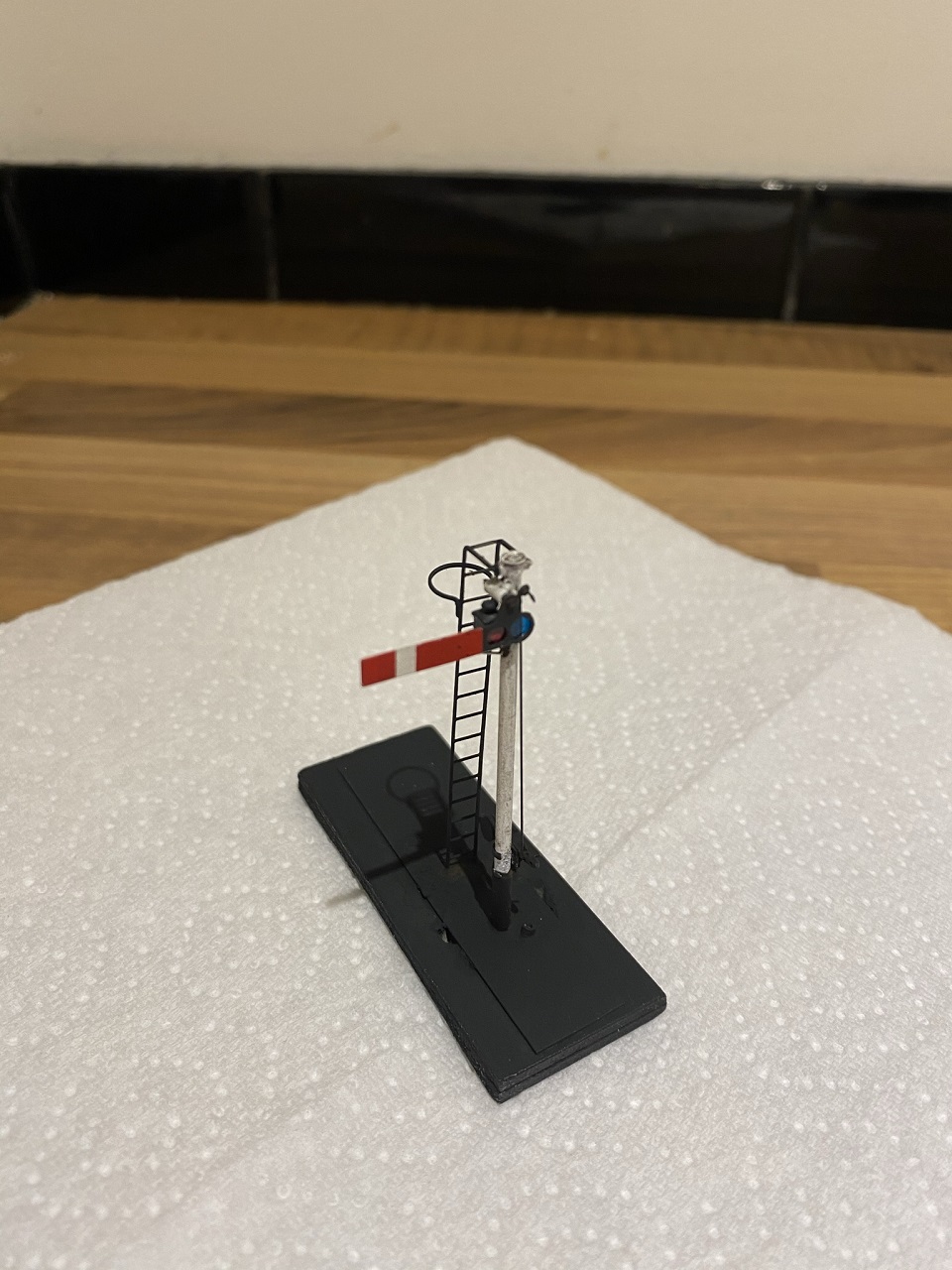
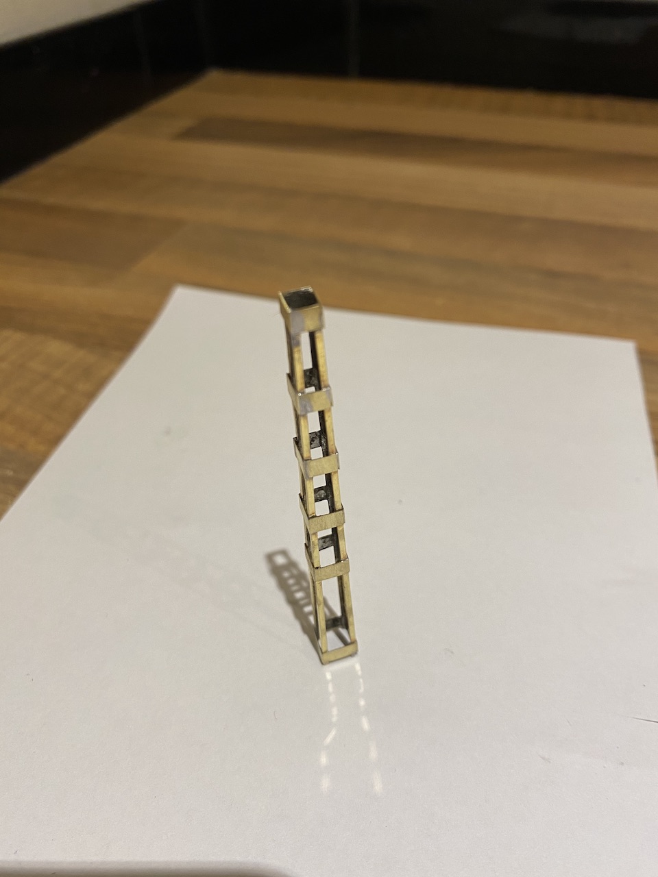
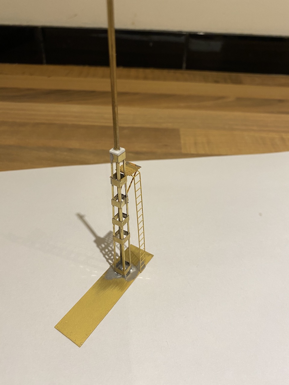
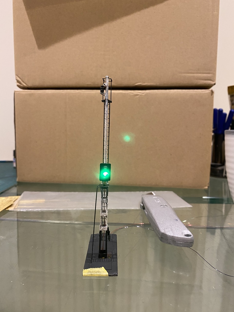
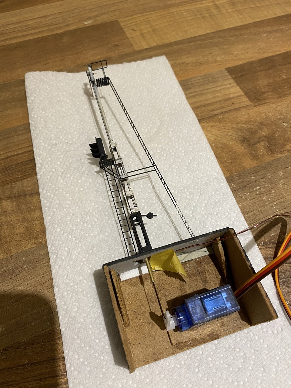
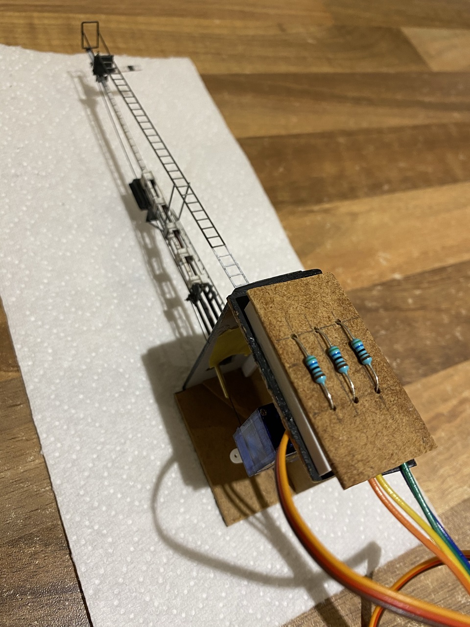
Only the second signal I've ever built and I'm pretty happy with it.

Image

User avatar
John Donnelly
Web Team
Posts: 1091
Joined: Fri Mar 16, 2012 7:03 pm

Re: Signalling for South Pelaw Junction

Postby John Donnelly » Thu Jan 28, 2021 8:31 pm

And it is done, apart from the back blinder which I'll only add once the servo has been attached and I'm happy that I won't need to remove the arm...

Image

Only 30 or so to go...

User avatar
Serjt-Dave
Posts: 641
Joined: Tue Oct 02, 2012 3:31 pm

Re: Signalling for South Pelaw Junction

Postby Serjt-Dave » Fri Jan 29, 2021 9:20 am

That's looking very sweet and made in just a day, well done. So theoretically you could have to other 30 done my the end of February just as lockdown finishes {we hope} and you'll be able to plant then on your layout. Jobs a good'un. LOL.

I don't have as many as you to build but like yourself I've never made them before, but I must get round and make a start on them even if it's just working out how they are going to be fitted on to the baseboards etc. At least I can then continue working around the signal bases doing scenic/ ballasting etc. I have four ground signals to do and make work and three of them are the flappy front type.

Looking forward to seeing how you attach the servo and mechanism.

Keep Safe

Dave

User avatar
John Donnelly
Web Team
Posts: 1091
Joined: Fri Mar 16, 2012 7:03 pm

Re: Signalling for South Pelaw Junction

Postby John Donnelly » Fri Jan 29, 2021 3:39 pm

Thanks Dave.

I'm no engineer so I've kept things very simple with the servo mount, just 3 bits of MDF and the servo is glued to that - if it fails in the future it should just snap off for replacement although, certainly for those signals with multiple arms I'll come up with another way to attach the servo.


Next up is this signal, a tall tubular post with additional support at the bottom from a square metal framework. In the 1950's there was also a distant arm on the same post but, as shown in the photo, this was replaced with a 3 aspect colour light.

Image

User avatar
Winander
Posts: 842
Joined: Thu Mar 20, 2014 12:19 pm

Re: Signalling for South Pelaw Junction

Postby Winander » Fri Jan 29, 2021 6:06 pm

Hello John,

It's looking very good. What are you using to control the servo?

thanks
Richard Hodgson
Organiser Scalefour Virtual Group. Our meeting invitation is here.

User avatar
John Donnelly
Web Team
Posts: 1091
Joined: Fri Mar 16, 2012 7:03 pm

Re: Signalling for South Pelaw Junction

Postby John Donnelly » Fri Jan 29, 2021 6:14 pm

Thanks Richard,

For the purpose of the video, I just used this servo tester I got from eBay:

Image

On the layout, I'm using MERG Servo 4 control boards with DCC Concepts Cobalt levers.

John

User avatar
John Donnelly
Web Team
Posts: 1091
Joined: Fri Mar 16, 2012 7:03 pm

Re: Signalling for South Pelaw Junction

Postby John Donnelly » Tue Feb 16, 2021 8:42 am

I've made a start on the next signal which has a base of angle and strip rather than a tubular post. I believe that Alan Gibson does an etch for this but I thought I'd have a crack at scratch building it. My soldering experience is still rather limited and I suspect that this would have been an ideal candidate for a resistance soldering iron as I had numerous joints come apart but 28 parts later, I have this:

Image

There are some thinner straps still to add but, as they are not structural, I'm leaning towards adding them with styrene strip and super glue instead...

User avatar
Paul Willis
Forum Team
Posts: 3031
Joined: Sun Jul 20, 2008 6:00 pm

Re: Signalling for South Pelaw Junction

Postby Paul Willis » Tue Feb 16, 2021 6:31 pm

John Donnelly wrote:There are some thinner straps still to add but, as they are not structural, I'm leaning towards adding them with styrene strip and super glue instead...


That makes a lot of sense, given that it will all be the same under a coat of paint and a spot of weathering.

Nice work. As ever, practice makes perfect with soldering.

Cheers
Paul
Beware of Trains - occasional modelling in progress!
www.5522models.co.uk

User avatar
John Donnelly
Web Team
Posts: 1091
Joined: Fri Mar 16, 2012 7:03 pm

Re: Signalling for South Pelaw Junction

Postby John Donnelly » Tue Feb 16, 2021 8:13 pm

Thanks Paul, more progress made today:

Image

User avatar
John Donnelly
Web Team
Posts: 1091
Joined: Fri Mar 16, 2012 7:03 pm

Re: Signalling for South Pelaw Junction

Postby John Donnelly » Thu Feb 18, 2021 8:19 pm

Some more progress. As with all things, I think there are bits that could be improved but, in the overall context of a 40' long layout that I'm building pretty much solo, it is more than acceptable for me.

Clean up needed and more details to add but it is getting there...

Image

User avatar
John Donnelly
Web Team
Posts: 1091
Joined: Fri Mar 16, 2012 7:03 pm

Re: Signalling for South Pelaw Junction

Postby John Donnelly » Thu Feb 25, 2021 9:28 pm

Still some details to be added but the signal has now had the colour light head fitted and has been painted.

Image

Image

On the next one, I plan on doing a better job on the ladders and will thicken up the edges...

User avatar
John Donnelly
Web Team
Posts: 1091
Joined: Fri Mar 16, 2012 7:03 pm

Re: Signalling for South Pelaw Junction

Postby John Donnelly » Tue Mar 09, 2021 10:20 pm

Operating wires and servo installed:

Image

I've never done any work with components that use enamelled wire before so I have no idea how robust it is. I didn't therefore, want to take any chances with is so, to connect the colour light head to the electrics, I made up a small board with all the connections underneath which keeps the enamelled wire out of the way with no chance of anyone catching it once the signal has been installed:

Image

and with that done, the driver can now proceed with caution:

Image

Still some small details, like the crank, to add, touching up to do and to try and get the wires hidden in one of the corners of the base support and it'll be complete...

User avatar
Andy W
Posts: 884
Joined: Thu May 21, 2009 8:11 am

Re: Signalling for South Pelaw Junction

Postby Andy W » Wed Mar 10, 2021 2:42 pm

Lovely
Make Worcestershire great again.
Build a wall along the Herefordshire border and make them pay for it.

User avatar
John Donnelly
Web Team
Posts: 1091
Joined: Fri Mar 16, 2012 7:03 pm

Re: Signalling for South Pelaw Junction

Postby John Donnelly » Thu Mar 11, 2021 10:35 pm

Thanks Andy.

As far as control for the turnouts and signals is concerned, it has always been my plan to operate them from a lever frame to replicate the prototype signal box. This involves a lot of levers and I'm going to be using the DCC Concepts Cobalt levers, not cheap by any stretch of the imagination but they are pretty much plug and play and represent a huge time saving over, say, constructing the frame from the Society kit.

As part of the control process and using experience gained by working as signalman on the EM gauge version of South Pelaw, I've been working on the signalling diagram and, using a drawing program called Inkscape, have come up with the diagram below. Everything is numbered to correspond with the relevant lever in the frame, turnouts are light grey circles, signals are dark gray and ground signals are red. Each signal number has a representation of the signal itself next to it. This is very much an initial draft and I will be adding locations for LEDs the show the turnout and signal settings.

Image

davebradwell
Posts: 1173
Joined: Fri Jan 18, 2019 3:48 pm

Re: Signalling for South Pelaw Junction

Postby davebradwell » Fri Mar 12, 2021 9:48 am

All very nice but does it show the rest position of points when levers are in the frame - or have I missed some subtlety? Some of these won't be obvious as they will reflect safety rules. You could just use a line of toggle switches for a temporary frame and build the real thing later when you realise how useful interlocking is.

DaveB

User avatar
John Donnelly
Web Team
Posts: 1091
Joined: Fri Mar 16, 2012 7:03 pm

Re: Signalling for South Pelaw Junction

Postby John Donnelly » Fri Mar 12, 2021 1:18 pm

Thanks for that Dave.

Interlocking (electronic) is certainly in the future plans. As for the point positions, I was just going to have LEDs in the appropriate positions on the diagram to show the current setting.

User avatar
grovenor-2685
Forum Team
Posts: 3917
Joined: Sun Jun 29, 2008 8:02 pm

Re: Signalling for South Pelaw Junction

Postby grovenor-2685 » Fri Mar 12, 2021 1:26 pm

A signal box diagram usually shows the points normal position, plenty of examples on the web.
Just looks more realistic, the LEDs are an option not usually provided with mechanical frames except when the points are motor worked.
Also helps so you connect the levers to the points the right way round. ie points normal when lever normal.
Regards
Keith
Grovenor Sidings

User avatar
John Donnelly
Web Team
Posts: 1091
Joined: Fri Mar 16, 2012 7:03 pm

Re: Signalling for South Pelaw Junction

Postby John Donnelly » Fri Mar 12, 2021 1:46 pm

Ah right, I see what was meant now.

I'll just be relying on LEDs, the diagram is as much to help any operators unfamiliar with which levers control which turnouts as anything else...

davebradwell
Posts: 1173
Joined: Fri Jan 18, 2019 3:48 pm

Re: Signalling for South Pelaw Junction

Postby davebradwell » Fri Mar 12, 2021 3:12 pm

Being able to glance at the frame and see that all is safe as a train rolls in is invaluable. I have a geographic diagram for my NCB yard (which would have had hand levers) and we're regularly going the wrong way or, worst of all, running into the crossing end of a wrongly set point and shutting all the power down. It's that quick glance versus checking each point separately on the diagram. Think how much time you'll save by not installing all those LEDs and just showing normal on the diagram. It was probably fundamental to the safety of the prototype and difficult to appreciate if you haven't experienced it. Doesn't the EM version have a frame?

DaveB

User avatar
John Donnelly
Web Team
Posts: 1091
Joined: Fri Mar 16, 2012 7:03 pm

Re: Signalling for South Pelaw Junction

Postby John Donnelly » Fri Mar 12, 2021 5:12 pm

Thanks again Dave.

I’ll be honest I know next to nothing about how the prototype worked hence my not understanding your original reply fully.

The EM version has rotary switches on the panel that show the direction of the turnout as well as LEDs to show the same.

John

davebradwell
Posts: 1173
Joined: Fri Jan 18, 2019 3:48 pm

Re: Signalling for South Pelaw Junction

Postby davebradwell » Fri Mar 12, 2021 9:22 pm

Sounds like you'll need to think about it to get over the shock but the nearer you are to the prototype way of doing things, then the better the results. You just need 80 sub min toggle switches, or even your Cobalts, in a row - you might be able to miss a few out. Ditch the LEDs and all the wiring because they don't add anything. Looks like you've copied the prototype numbering so you'll find they fall into patterns as you set up routes. Paint the toggles the correct lever colours.

I'm assuming you're DCC with this lot but despite going back through the thread I didn't spot a reference. With no section switches it removes any need for the geographical panel.

When all this hassle is over, try and find a layout with interlocking to operate and you'll realise what a difference it makes, especially in reducing signalman's errors. Obviously not a pressing matter at the moment but may be relevant to long term planning.

DaveB

User avatar
John Donnelly
Web Team
Posts: 1091
Joined: Fri Mar 16, 2012 7:03 pm

Re: Signalling for South Pelaw Junction

Postby John Donnelly » Fri Mar 12, 2021 10:06 pm

Thanks again for the feedback, it is appreciated.

davebradwell wrote:Sounds like you'll need to think about it to get over the shock but the nearer you are to the prototype way of doing things, then the better the results. You just need 80 sub min toggle switches, or even your Cobalts, in a row - you might be able to miss a few out. Ditch the LEDs and all the wiring because they don't add anything. Looks like you've copied the prototype numbering so you'll find they fall into patterns as you set up routes. Paint the toggles the correct lever colours.


Toggle switches would certainly be cheaper but I do like the idea of a 'proper' lever frame and the plan always was to paint the levers the appropriate colours. There will certainly be some missing - some of track shown in the diagram, like the colliery sidings, had gone in the period I am modelling.

davebradwell wrote:I'm assuming you're DCC with this lot but despite going back through the thread I didn't spot a reference. With no section switches it removes any need for the geographical panel.


Loco control is DCC but the turnouts and signals are controlled using MERG Servo 4 boards.

davebradwell wrote:When all this hassle is over, try and find a layout with interlocking to operate and you'll realise what a difference it makes, especially in reducing signalman's errors. Obviously not a pressing matter at the moment but may be relevant to long term planning.


The EM version of South Pelaw, which I enjoy operating as signalman on, has full, prototypical, interlocking so I know what a difference it makes...

davebradwell
Posts: 1173
Joined: Fri Jan 18, 2019 3:48 pm

Re: Signalling for South Pelaw Junction

Postby davebradwell » Sat Mar 13, 2021 12:00 pm

It sounds like the EM model has something more like the early BR panels when semaphore signals were eliminated. Rather a different feel to them.

You don't have to justify what you're doing, John - it's your model - I'm just pointing out you might be missing something by combining technologies. You'll have gathered I have developed a hatred of geographical control panels since making one and it will be ditched as soon as I can move the layout into a slightly larger space. The temporary toggle switches across the aisle at Derwenthaugh can then be replaced by the frame I made 2 years ago.

DaveB

User avatar
John Donnelly
Web Team
Posts: 1091
Joined: Fri Mar 16, 2012 7:03 pm

Re: Signalling for South Pelaw Junction

Postby John Donnelly » Mon Mar 15, 2021 10:08 am

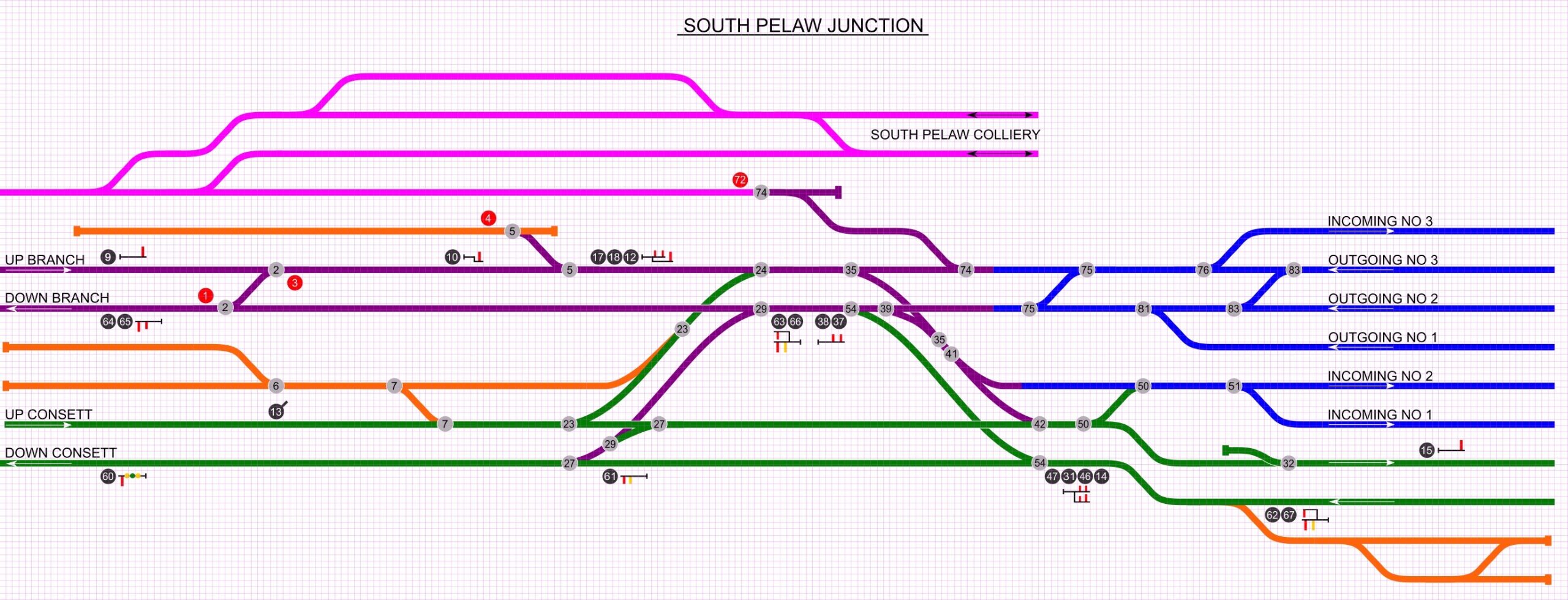
davebradwell wrote:It sounds like the EM model has something more like the early BR panels when semaphore signals were eliminated. Rather a different feel to them.

You don't have to justify what you're doing, John - it's your model - I'm just pointing out you might be missing something by combining technologies. You'll have gathered I have developed a hatred of geographical control panels since making one and it will be ditched as soon as I can move the layout into a slightly larger space. The temporary toggle switches across the aisle at Derwenthaugh can then be replaced by the frame I made 2 years ago.

DaveB


Reading your latest post, I wonder if perhaps, I haven't been completely clear as to my intentions.

The panel for the EM version is geographical, the turnout and signal switches are placed on the panel at the appropriate locations.

However, I plan on having a 'proper' lever frame as per the prototype signal box with all the levers in the correct order. The diagram I'm developing will be separate and used solely to show an indication of how the turnouts and signals are set, it will have no controls on it, just LED indicators. Having researched the prototype for a number of years and having operated as a signalman on the EM version, I suspect that I could probably get away without the diagram but I want other people to be able to come along and work the signal box without having an intimate knowledge of the location.

John

davebradwell
Posts: 1173
Joined: Fri Jan 18, 2019 3:48 pm

Re: Signalling for South Pelaw Junction

Postby davebradwell » Mon Mar 15, 2021 11:00 am

Yes, that's what I thought you meant - I was merely suggesting that you might save yourself the tedious effort of wiring up a load of LEDs by a simple change of graphic. It is, after all, how a normal semaphore installation was worked and I've found layouts based on this to be simple and accurate in use, even for new operators. You'd need to copy the normal positions of points from the prototype - they had no lights, just the position of the lever, generally, and it works very well. You might as well try it before installing the LEDs as you've nothing to lose.

There was a further suggestion that if you reduced your initial outlay by using cheap switches then you might feel inclined at a later date to upgrade to an interlocked frame.

Just a comment on dcc wiring - a friend is currently tearing his hair out trying to find a fault on a complex layout that is all one section. It's a reminder to arrange for wiring to be easily broken down into sections for fault finding.

DaveB


Return to “John Donnelly”

Who is online

Users browsing this forum: ClaudeBot and 0 guests