P4 conversion work

Colin Parks

Re: Starting out in P4

Postby Colin Parks » Sat Oct 11, 2014 4:32 pm

Martin Wynne wrote:
Colin Parks wrote:But I am confused: when fitting the check chairs, is the left hand side judged to be when looking from the inside or outside of the track?

Hi Colin,

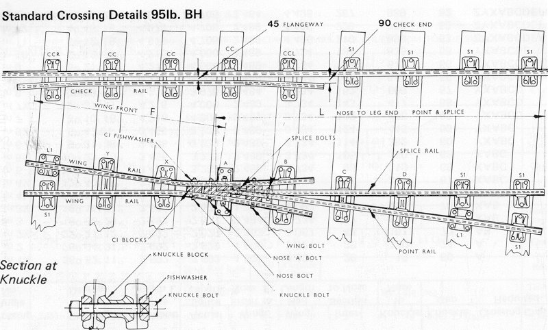
Stand on the end of the timber and look down on the check rail. CCL is on the left, CCR is on the right:

Image

There is more in this drawing than first meets the eye. You can see that where the rail is inclined, the outer edge of the rail foot is shown. Where the rail is vertical, the foot can't be seen. You can see between the B and C chairs that there is a twist in the rail so that the point and splice rails are vertical at the vee nose and inclined for the remainder of their length. Note also the use of L1 bridge chairs where there isn't room for two ordinary S1 chairs.

regards,

Martin.


I must be getting close to having it all correct now Martin. All the handed chairs are definitely in the right place now and sighting down each run of five check chairs, the bases are in the same plane, with the 'CC' feeds from where they were joined to the sprue, all on the same side.
What is most interesting about that diagram you posted is the twist in the point and splice rails. This is the answer to the question I had when first shaping the rails for the double slip's common crossings: How can two rails, inclined at 20 degrees, be shaped at their tips to form the vee without a gap in the joint? Well the fact is that they are vertical at the tip as you say. I fear my common crossings have angled wing rails but vertical point and splice rails!

The L1 and S1 chairs are easy enough, as I have the C&L downloads for (everything but the check rail) chairing.

All the best,

Colin

Colin Parks

Re: Starting out in P4

Postby Colin Parks » Sat Oct 11, 2014 4:44 pm

In terms of seeing which "hand" the CCL and CCRs are (ie which of the jaws has the angle on it and which rail is the inclined one) - even under strong magnification it is very hard to "see" it - the best way is to push them onto a bit of rail and see which way they want to point. Then, make a little drawing of the sprue and mark on it which end of which chair points which way - remembering that (in the model version) there is a left and a right hand of both CCL and CCR (depending on which way the key points) and that only one of the two jaws in each is moulded at the flare angle :? You may well decide that in practice it makes b*gg*r all difference :D

Another challenge is to make sure that the flare angles of the rail are bent spot-on and the chairs sit exactly the right distance along the flare - which means your timbers must be in in exactly the right place otherwise the chairs will overhang the timbers... - all in all a bit of a tussle but well worth the effort.

The bowing of these chairs can result from mis-threading them so that the inclinations fight each other as Martin suggests, but much of it is down to the too-thick web of "modern" rail - 1970's vintage Studiolith rail fits perfectly!! Poor old Len spent an age getting these chairs spot on, so we owe it to him to learn how to get the most of them, but equally, their geometry is ultimately only as good as that of the rail which - in my experience - is a very variable quantity these days despite the best efforts of our suppliers who are in the hands of their wire-drawers.

Just to mention that the way I thread them up is to put them all onto the check rail (in their correct positions) first - that way (in theory) you end up with a straight line of chair jaws through which the running rail can be pushed.

One small problem I did have with these when my track first went under traffic, was that the check rails had a tendency to creep out of the chairs initially. This might well have been because I did not take enough care in getting things right, but initially it did cause issues because it could result in the check gauge going tight (due to the movement of the flare bend towards the running rail) if not attended to. Since I have painted and weathered the track it all seems to have stopped...

Can I say in passing Colin, that I am really impressed by the patience which you are taking to get this slip right - well done for that and I am sure that you will be rewarded with some excellent running and appearance in the finished job. It seems that the apprenticeship you served on Newhaven Harbour (00) has stood you in excellent stead :thumb

Very Best Wishes,


Hi Howard,

I did resort to your method in the end to test the flared chairs with a short length of rail. All is now well - I hope. This track-building lark is quite a subtle business and nothing like knocking an SMP plastic-based point kit together at all!
At present my check rails are slightly too far from the stock rail judging by using the flangeway gauge. I suspect that once the check chairs are sitting flat on the sleepers this will tighten up to the correct clearance. I had thought of using a spot of Loctite to lock the check rails in position, but it seems that paint will do the job just as well.

All the best,

Colin

User avatar
Martin Wynne
Posts: 1172
Joined: Mon May 14, 2012 4:27 pm

Re: Starting out in P4

Postby Martin Wynne » Sat Oct 11, 2014 5:04 pm

Colin Parks wrote:At present my check rails are slightly too far from the stock rail judging by using the flangeway gauge.

Hi Colin,

The gap between the stock rail and the check rail doesn't matter and you should not use the flangeway gauge to test it. The important dimension is the check gauge -- from the check rail to the opposite running rail. Set your check rail + running rail assemblies using the check gauge tool from the opposite rail:

Image

Notes about this diagram are here: http://85a.co.uk/forum/view_postx.php?post_id=15021

Martin.
40+ years developing Templot. Enjoy using Templot? Join Templot Club. Be a Templot supporter.

Colin Parks

Re: Starting out in P4

Postby Colin Parks » Sat Oct 11, 2014 5:23 pm

Martin Wynne wrote:
Colin Parks wrote:At present my check rails are slightly too far from the stock rail judging by using the flangeway gauge.

Hi Colin,

The gap between the stock rail and the check rail doesn't matter and you should not use the flangeway gauge to test it. The important dimension is the check gauge -- from the check rail to the opposite running rail. Set your check rail + running rail assemblies using the check gauge tool from the opposite rail:

Image

Notes about this diagram are here: http://85a.co.uk/forum/view_postx.php?post_id=15021

Martin.


Hi Martin,
I will be using the correct gauges in the correct places when I finally get around to fixing the rail sub-assemblies in position!

All the best,

Colin

User avatar
grovenor-2685
Forum Team
Posts: 3923
Joined: Sun Jun 29, 2008 8:02 pm

Re: Starting out in P4

Postby grovenor-2685 » Sat Oct 11, 2014 7:48 pm

Of course, if you are using the check rail chairs then the gap at the check rail is fixed, you then have the choice of fixing them in place using a track gauge on the running rail or a check gauge on the checkrail. Unless the radius is tight enough to need gauge widening both methods should both give the same result.
Regards
Keith
Regards
Keith
Grovenor Sidings

Colin Parks

Re: Starting out in P4

Postby Colin Parks » Sun Oct 12, 2014 9:35 am

grovenor-2685 wrote:Of course, if you are using the check rail chairs then the gap at the check rail is fixed, you then have the choice of fixing them in place using a track gauge on the running rail or a check gauge on the checkrail. Unless the radius is tight enough to need gauge widening both methods should both give the same result.
Regards
Keith


Hi Keith,

Yes, the check-rail chairs do hold the rail at the standard 0.68mm according to my gauges, so I am not going to fiddle about with anything there.

I have several gauges at my disposal for when I get around to fixing everything down. There is a set of Exactoscale gauges which are graded from 0 - + 0.3mm, the check gauge and also a triangular S4 Stores gauge. The latter I had intended to use for situations where gauge-widening was needed, but it is unclear to me if such a gauge will work with inclined rails. (I have read tales of the rails springing inwards after triangular gauges are used with plastic chaired track, as they were designed for 'vertical rail' track construction.)
Having read up on various people's methods and advice, I had intended to have + 0.1mm gauge-widening through the switches of this double slip - even though it is built to generous proportions. The common crossings will be set to gauge using the check gauge, It seems too complicated and unnecessary to attempt gauge-widening in that area.

All the best,

Colin

User avatar
James Moorhouse
Posts: 129
Joined: Tue Jul 22, 2008 8:50 pm

Re: Starting out in P4

Postby James Moorhouse » Sun Oct 12, 2014 10:20 am

Hi Colin,

In Scalefour News 178 (available in the Scalefour News Archive) there was a report on a derailment on Steve Hall's Drighlington layout. It concluded that a check (rail) gauge had not been correctly utilized when constructing the turnout on which the derailment occurred. In response to the accident report there was a letter in the subsequent issue from Andrew Jukes about the Exactoscale check chairs and what flangeway dimension the chairs actually give, with some useful notes on how to use the check chairs.

On the subject of “check rail creep”, have you considered making your check rails live (surprised Martin Wynne hasn’t already mentioned this)? This may provide an opportunity to anchor your check rails.

Excellent work on the slip. I look forward to seeing the addition of the third rail and side entry/exit ramps!

Simon Glidewell

Re: Starting out in P4

Postby Simon Glidewell » Sun Oct 12, 2014 10:36 am

Hello Colin,

Great to read about your P4 progress! Looking forward to future photos, etc.

All the best
Simon

Colin Parks

Re: Starting out in P4

Postby Colin Parks » Sun Oct 12, 2014 11:09 am

James Moorhouse wrote:Hi Colin,

In Scalefour News 178 (available in the Scalefour News Archive) there was a report on a derailment on Steve Hall's Drighlington layout. It concluded that a check (rail) gauge had not been correctly utilized when constructing the turnout on which the derailment occurred. In response to the accident report there was a letter in the subsequent issue from Andrew Jukes about the Exactoscale check chairs and what flangeway dimension the chairs actually give, with some useful notes on how to use the check chairs.

On the subject of “check rail creep”, have you considered making your check rails live (surprised Martin Wynne hasn’t already mentioned this)? This may provide an opportunity to anchor your check rails.

Excellent work on the slip. I look forward to seeing the addition of the third rail and side entry/exit ramps!


Hi James,

I think I have read that article in the archived S4 News. I shall have a look at the letter you mention. The check rails on my point seem a little 'slack' at present. I am going to wait until the chairs are firmly stuck to the sleepers and measure again. The subject of check chairs/rails is a far more complex subject than I had at first assumed. I like the idea on bonding the check rails to the stock rails, but would it make adjustment more difficult at a later stage I wonder?

Re. the third rail etc.: the insulators and side protection board brackets will be fitted in due course. I have bought cast side entry ramps from the S4 Stores and very nice they look too. There is a long way to go before those can be fitted though!

All the best,

Colin

Colin Parks

Re: Starting out in P4

Postby Colin Parks » Sun Oct 12, 2014 11:14 am

Simon Glidewell wrote:Hello Colin,

Great to read about your P4 progress! Looking forward to future photos, etc.

All the best
Simon


Hi Simon,

You are back!!!!!!!!!!!!

Strange, I was just about to email you re. SR coach bogies. Peter's Spares have the Hornby ones in stock http://www.petersspares.com/hornby-x972 ... -wheels.ir They are the bees knees in my opinion.

All the best,

Colin

User avatar
James Moorhouse
Posts: 129
Joined: Tue Jul 22, 2008 8:50 pm

Re: Starting out in P4

Postby James Moorhouse » Sun Oct 12, 2014 11:33 am

Colin Parks wrote:I have bought cast side entry ramps from the S4 Stores and very nice they look too. There is a long way to go before those can be fitted though!


I think you might be mistaken; Scalefour Stores does not sell any side entry/exit ramps. The cast ramps they do sell are intended for London Transport modellers. The third rail side ramps I refer to are featured in Russ Elliott's "3rd and 4th Rail Dimensions and Settings" (http://homepage.ntlworld.com/russelliott/3rd-4th.html) about halfway down the page. I reckon the best way of modelling these will be to use some brass, or preferably nickel silver, angle.

Simon Glidewell

Re: Starting out in P4

Postby Simon Glidewell » Sun Oct 12, 2014 2:00 pm

Hello James,

I used the Scalefour Society ramps on my layout St. Mary Hoo to create side exit ramps; I just filed the brass castings down one side, at a suitable angle in relation to the turnout road angle, and soldered them onto Scalefour Society conductor rail. These had to be sited accurately as my third rail works like the prototype and is energised. The ramp angle is more gentle than used on the southern region (I'm sure there are exceptions out there somewhere though) but the effect is very realistic, especially when watching the sprung pick ups engaging with the ramp. By using these castings you get the nice bolt detail on the outside.

Cheers
Simon

Edited today; photo removed so as not to hijack Colin's thread and to add the missing info - "side exit ramps".
Last edited by Simon Glidewell on Mon Oct 13, 2014 7:49 am, edited 1 time in total.

User avatar
grovenor-2685
Forum Team
Posts: 3923
Joined: Sun Jun 29, 2008 8:02 pm

Re: Starting out in P4

Postby grovenor-2685 » Sun Oct 12, 2014 2:32 pm

(I have read tales of the rails springing inwards after triangular gauges are used with plastic chaired track, as they were designed for 'vertical rail' track construction.)

this has been discussed before, the original P4 triangular guages do not hold the rail vertical, the rail foot does not enter the slots in the gauge which therefore acts only on the head and works fine with the 1:20 rail inclination. Of course this is not neccessarily true of every batch of these gauges made over the years, so if the slots in yours are so deep as to hold the rail foot you should file back the sides of the slots to eliminate the problem.
Regards
Keith
Regards
Keith
Grovenor Sidings

Simon Glidewell

Re: Starting out in P4

Postby Simon Glidewell » Sun Oct 12, 2014 2:53 pm

Colin Parks wrote:
Simon Glidewell wrote:Hello Colin,

Great to read about your P4 progress! Looking forward to future photos, etc.

All the best
Simon


Hi Simon,

You are back!!!!!!!!!!!!

Strange, I was just about to email you re. SR coach bogies. Peter's Spares have the Hornby ones in stock http://www.petersspares.com/hornby-x972 ... -wheels.ir They are the bees knees in my opinion.

All the best,

Colin


Many thanks for the info Colin regarding the Hornby bogies. When I last checked his site he only had the ones with pick up shoes.

Cheers
Simon

Colin Parks

Re: Starting out in P4

Postby Colin Parks » Sun Oct 12, 2014 5:34 pm

This afternoon's entertainment was to fold up the stretcher bar brackets.

There was, I admit, some swearing. The Ambis etched fret comes with no instructions and the only reference available is a slightly out of focus picture on their website. Somehow it suddenly clicked and I was able to fold up the sixteen parts - eventually! The stretcher bars themselves will be made from strips of 0.2mm GEL material (Glass Epoxy Laminate) - as per the 'JFS method'.

IMG_1671.JPG


I have soldered a spare bracket to a piece of rail just to see how it would look. There is no location for the bracket to sit in the rail web. JFS (Howard) has suggested to file grooves on the backs so that they fit over the rail foot. The clearance between the top of the bracket and wheel flanges is breathtakingly small but just sufficient. On the upside, the bracket is very firmly attached to the rail, which is just what I want!

IMG_1669.JPG


There are still no drive rod attachments for the stretchers. The fret of parts contains extended brackets which might be for that purpose. I tried and failed to fold one of these longer types. Any ideas anyone?!

IMG_1672.JPG


Colin
You do not have the required permissions to view the files attached to this post.

JFS
Posts: 813
Joined: Wed Dec 16, 2009 3:47 pm

Re: Starting out in P4

Postby JFS » Sun Oct 12, 2014 8:33 pm

Hello Colin,

Not exactly sure what Alan had in mind, but here is a photo of a drive stretcher (it is one of Martin W's - so I hope you do not mind me re-posting it Martin) and it rather looks like simply putting a right angle bend just before the eye at the end might produce something which looks a bit like this to do the job. Not sure if there is a half etched fold line on the back which indicates this?

Stretcher drive 1.jpg


BTW, ignore the "drive" in the foreground - that is just there to do the job of the FPL - it is the stretcher which we can see the back of which is of interest.

One thing which is a complete PITA for double slips is the FPL stretcher as they need a drop end to go under the opposing road

Very Best Wishes,
You do not have the required permissions to view the files attached to this post.

User avatar
Paul Willis
Forum Team
Posts: 3046
Joined: Sun Jul 20, 2008 6:00 pm

Re: Starting out in P4

Postby Paul Willis » Mon Oct 13, 2014 5:10 am

Colin Parks wrote:This afternoon's entertainment was to fold up the stretcher bar brackets.

There was, I admit, some swearing. The Ambis etched fret comes with no instructions and the only reference available is a slightly out of focus picture on their website.


Hi Colin,

Are you sure that these aren't the instructions?

http://ambisengineering.co.uk/pc4_4.pdf

They've available as a very useful download, as are a number of other sheets to do with point construction.

http://www.ambisengineering.co.uk/Downloads_and_details.htm

HTH
Flymo
Beware of Trains - occasional modelling in progress!
www.5522models.co.uk

Terry Bendall
Forum Team
Posts: 2427
Joined: Sun Jul 27, 2008 7:46 am

Re: Starting out in P4

Postby Terry Bendall » Mon Oct 13, 2014 6:18 am

Simon Glidewell wrote:I used the Scalefour Society ramps on my layout St. Mary Hoo; I just filed the brass castings down one side, at a suitable angle in relation to the turnout road angle, and soldered them onto Scalefour Society conductor rail. These had to be sited accurately as my third rail works like the prototype and is energised. The ramp angle is more gentle than used on the southern region (I'm sure there are exceptions out there somewhere though) but the effect is very realistic,


My impression was that the Society ramps were intended for 4th rail electrification, e.g London Undergrtound, since the Southern system did not use such things - the conductor rail was bent down to form a ramp. When we were building Elcot Road we had access to some very useful pictures of Addiscombe which was used as part of the prototype inspiration and checking the pictures now, there are no ramps evident. We also has access to some official Network Rail information on key dimenisons for third rail instalations and from this I extracted the following information about ramps (measurements conversted to 4mm scale)
Ramps - two bend type 1 in 48 slope for 32 mm and I in 24 for 8mm End is 1mm below top of rail.
Single bend type 1 in 48 slope end is 0.84 mm below top of rail

Some people will be aware that the ends of the conductor rail are bent away from the running rail as well as downwards.

Of course making the third rail functional, as Simon has done, may make it necessary to use other methods. We did not intend to do this on Elcot Road but the pick up shoes on the Bachmann 2EPB units do just skim the surface of the conductor rail.

Terry Bendall

Simon Glidewell

Re: Starting out in P4

Postby Simon Glidewell » Mon Oct 13, 2014 7:04 am

Hello Terry,

All of what you say is absolutely true; however, what I was referring to (and Colin I believe) were side exit ramps on conductor rail over some point work, as can be seen in my photo. All the end ramps on my system are the usual bent conductor rail like Elcot Road. Some of my end ramps have a prototypical notch filed on the underside at the point of the main bend. I also have two different levels of incline on the ramps. With working pick ups side exit ramps over points are essential to prevent snagging and derailment. I just realised that I didn't state in my post above that I was referring to side exit ramps! Sorry for the confusion. Above post duly edited.

All the best
Simon

Colin Parks

Re: Starting out in P4

Postby Colin Parks » Mon Oct 13, 2014 3:12 pm

JFS wrote:Hello Colin,

Not exactly sure what Alan had in mind, but here is a photo of a drive stretcher (it is one of Martin W's - so I hope you do not mind me re-posting it Martin) and it rather looks like simply putting a right angle bend just before the eye at the end might produce something which looks a bit like this to do the job. Not sure if there is a half etched fold line on the back which indicates this?

Stretcher drive 1.jpg


BTW, ignore the "drive" in the foreground - that is just there to do the job of the FPL - it is the stretcher which we can see the back of which is of interest.

One thing which is a complete PITA for double slips is the FPL stretcher as they need a drop end to go under the opposing road

Very Best Wishes,


Hi Howard,

Thanks for the picture. Yes it could be that the longer stretcher bracket is designed to make that kind of component. I am still not sure. There are no other half-etches other than those in the picture.

All the best,

Colin

Colin Parks

Re: Starting out in P4

Postby Colin Parks » Mon Oct 13, 2014 3:14 pm

Flymo748 wrote:
Colin Parks wrote:This afternoon's entertainment was to fold up the stretcher bar brackets.

There was, I admit, some swearing. The Ambis etched fret comes with no instructions and the only reference available is a slightly out of focus picture on their website.


Hi Colin,

Are you sure that these aren't the instructions?

http://ambisengineering.co.uk/pc4_4.pdf

They've available as a very useful download, as are a number of other sheets to do with point construction.

http://www.ambisengineering.co.uk/Downloads_and_details.htm

HTH
Flymo


Thanks Flymo.

I hadn't seen the downloads on the Ambis website. I have had a look at the instructions and still do no understand how the longer etched bracket should look!

All the best,

Colin

Colin Parks

Re: Starting out in P4

Postby Colin Parks » Mon Oct 13, 2014 3:21 pm

My impression was that the Society ramps were intended for 4th rail electrification, e.g London Undergrtound, since the Southern system did not use such things - the conductor rail was bent down to form a ramp. When we were building Elcot Road we had access to some very useful pictures of Addiscombe which was used as part of the prototype inspiration and checking the pictures now, there are no ramps evident. We also has access to some official Network Rail information on key dimenisons for third rail instalations and from this I extracted the following information about ramps (measurements conversted to 4mm scale)
Ramps - two bend type 1 in 48 slope for 32 mm and I in 24 for 8mm End is 1mm below top of rail.
Single bend type 1 in 48 slope end is 0.84 mm below top of rail

Some people will be aware that the ends of the conductor rail are bent away from the running rail as well as downwards.

Of course making the third rail functional, as Simon has done, may make it necessary to use other methods. We did not intend to do this on Elcot Road but the pick up shoes on the Bachmann 2EPB units do just skim the surface of the conductor rail.

Terry Bendall

Hi Terry,

I also have some of the society's ramps and will do just as Simon has done and use them as side-entry ramps. The junction at Newhaven Harbour is peppered with them! The castings might be intended for other purposes, but will add the finishing touch to point work fitted with a third rail.

All the best,

Colin
Last edited by grovenor-2685 on Mon Oct 13, 2014 7:35 pm, edited 1 time in total.
Reason: Edited to include start of quote, this is automatic if you use the BBcode buttons! Keith

JFS
Posts: 813
Joined: Wed Dec 16, 2009 3:47 pm

Re: Starting out in P4

Postby JFS » Mon Oct 13, 2014 6:16 pm

Terry Bendall wrote:Some people will be aware that the ends of the conductor rail are bent away from the running rail as well as downwards.


Really? This is news to me and I would be interested to see the official information on this.

Best wishes,

User avatar
James Moorhouse
Posts: 129
Joined: Tue Jul 22, 2008 8:50 pm

Re: Starting out in P4

Postby James Moorhouse » Mon Oct 13, 2014 7:23 pm

JFS wrote:
Terry Bendall wrote:Some people will be aware that the ends of the conductor rail are bent away from the running rail as well as downwards.


Really? This is news to me and I would be interested to see the official information on this.


Me too! After a quick trawl through the 'library', here's what I have on end ramps:

SRendramps.JPG


From the same folder (the contents of which emanated from the late Joe Brook Smith), here's something on side entry/exit ramps too. This drawing is why I suggested using nickel silver angle to model them.

SRsideramp.JPG


HTH. Sorry if this info is cluttering your thread, Colin!
You do not have the required permissions to view the files attached to this post.
Last edited by James Moorhouse on Wed Feb 28, 2018 11:41 pm, edited 1 time in total.

JFS
Posts: 813
Joined: Wed Dec 16, 2009 3:47 pm

Re: Starting out in P4

Postby JFS » Tue Oct 14, 2014 6:23 am

Colin Parks wrote:I hadn't seen the downloads on the Ambis website. I have had a look at the instructions and still do no understand how the longer etched bracket should look!

Colin


Hello Colin,

I think I get it - the long extensions with the hole in the end are bent back double against the sides of the bracket. They then form an eye-end under the stock rail. It is not the best way to do a double slip in truth, but many prototype turnouts are done that way - I will see if I can dig up a photo or two.

Very Best Wishes,


Return to “Colin Parks”

Who is online

Users browsing this forum: ClaudeBot and 0 guests