Hi all,
Having now started building points/turnouts one question i'd like to ask is,What is 1,2,3,4PL and 1,2,3,4PR where would i find them? and if not rtr how do i go about reproducing them as they are mentioned on the turnout plans that came from the society download section. I have previously built points/turnouts in the slightly narrower gauge being .6mm less than what i'm now trying to achieve!!!! And after reading Knuckles account i felt that it was time to do something about it!!!
Many thanks in advance,
Nick.
Building my first p4 points
-
steamraiser
- Posts: 561
- Joined: Thu Dec 31, 2009 4:49 pm
Re: Building my first p4 points
Nick,
Which points are you building ie A6 / B8 /C10?
And what system are you using - copperclad / ply & rivet / C&L or P4 Track Company?
Gordon
Which points are you building ie A6 / B8 /C10?
And what system are you using - copperclad / ply & rivet / C&L or P4 Track Company?
Gordon
-
ginger61
- Posts: 35
- Joined: Wed Jan 30, 2013 4:00 pm
Re: Building my first p4 points
steamraiser wrote:Nick,
Which points are you building ie A6 / B8 /C10?
And what system are you using - copperclad / ply & rivet / C&L or P4 Track Company?
Gordon
Many appologies for the slight error in not trying to say what i'm doing it in
Nick.
-
philchudley
- Posts: 34
- Joined: Wed Jul 30, 2008 10:36 am
Re: Building my first p4 points
These are the special chairs which are placed at the switch end of the turnout
The PL chairs are used on the left side of the turnout looking from the toe to the common crossing, whereas the PR chairs are used on the right hand side
These are used in addition to the usual slide chairs (known as P chairs). Exactoscale (now C&L) see sprues of these chairs (ref E4CH 501A) which cover A, B an C switches. These are numbered For example a 1PL is number 1 2PL is number 11 and 36, 1PR is number 3, 2PR is number 5 and 37. The numbers are on the sprue adjacent to the appropriate chair.
I have a useful document which shows the chair positions for LH, RH A, B and C switches and common crossings for 1:5 upto 1:10
If you will like a copy, please send a PM and I will scan it and send it to you or you can download from
http://www.finescale.org.uk/index.php?route=information/information&information_id=36
Hope this helps you move forward in you turnout making endeavours
Phil Chudley
-
ginger61
- Posts: 35
- Joined: Wed Jan 30, 2013 4:00 pm
Re: Building my first p4 points
Phil,
Many thanks for the info, I've now downloaded the relevant data sheets via your link. I see that there are only 4 actual slide chairs per pack so it looks like I'll have to use c&l slide chairs as well!!!! Once again many thanks.
Nick.
Many thanks for the info, I've now downloaded the relevant data sheets via your link. I see that there are only 4 actual slide chairs per pack so it looks like I'll have to use c&l slide chairs as well!!!! Once again many thanks.
Nick.
-
Martin Wynne

- Posts: 1172
- Joined: Mon May 14, 2012 4:27 pm
Re: Building my first p4 points
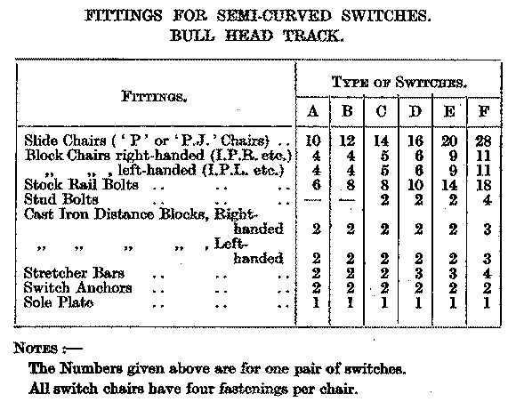
These are the special chairs used for REA semi-curved bullhead switches. The numbers are the total for the whole switch, i.e an A switch has 5 P chairs per switch blade.
P chairs are the ones on which the switch blade slides and to which the stock rail is fixed by means of a bolt through the rail web instead of a key. Block chairs come next and hold the both the switch blade and stock rail at the correct spacing (these are handed and numbered 1,2,3 etc.). The bolts and distance blocks fit between the rails to keep everything secure.
So for a B switch each side has (counting from the rail joint) :
2 standard chairs in front of the switch toe,
6 slide chairs,
4 block chairs,
Standard chairs and bridge chairs are then used as space on the timbers permits.
PJ chairs are a later design in which the outer jaw is in the form of a separate spacer block, similar to flat-bottom slide baseplates.
Martin.
40+ years developing Templot. Enjoy using Templot? Join Templot Club. Be a Templot supporter.
-
jayell
Re: Building my first p4 points
I see sole plates on photos of actual turnouts but they don't seem to be modelled. Is that because there is the risk of shorting across the rails? I am not sure what they actually do although I have read somewhere they are there to maintain the gauge at the toe.
John
John
-
grovenor-2685

- Forum Team
- Posts: 3923
- Joined: Sun Jun 29, 2008 8:02 pm
Re: Building my first p4 points
although I have read somewhere they are there to maintain the gauge at the toe.
Indeed that is what they do.
Some people model them, some don't, the further back you go in time the more likely your prototype didn't use them either.
A steel soleplate does hold an accurate gauge much longer than a bare timber so reducing maintenance costs.
Keith
-
Terry Bendall
- Forum Team
- Posts: 2428
- Joined: Sun Jul 27, 2008 7:46 am
Re: Building my first p4 points
ginger61 wrote:What is 1,2,3,4PL and 1,2,3,4PR where would i find them?
These are available in the Exactoscale range, now sold by C&L. It may well be possible to buy them separately, but I haven't looked. C&L will probably also have the other Exactoscale chairs needed for turnouts.
johnlewis wrote:I see sole plates on photos of actual turnouts but they don't seem to be modelled
Colin Craig includes these in his kits for flat bottom rail turnouts. Anyone who wants these for bull head rail turnouts may find that Colin will be prepared to sell you them as a separate item. He will be at Scaleforum so you could ask him then, otherwise see his web site.
Terry Bendall
-
grovenor-2685
- Forum Team
- Posts: 3923
- Joined: Sun Jun 29, 2008 8:02 pm
Re: Building my first p4 points
Here is a modelled soleplate from Howard Bolton's topic.

I think you will find some in the pics of Birmingham New Street in Jim's topics as well.
Regards
Keith
I think you will find some in the pics of Birmingham New Street in Jim's topics as well.
Regards
Keith
-
Martin Wynne
- Posts: 1172
- Joined: Mon May 14, 2012 4:27 pm
Re: Building my first p4 points
grovenor-2685 wrote:Some people model them, some don't, the further back you go in time the more likely your prototype didn't use them either.
A steel soleplate does hold an accurate gauge much longer than a bare timber so reducing maintenance costs.
Hi Nick,
Modelling them is tricky because the timber must be dropped below the level of the rest to accommodate the thickness of the sole plate underneath the chairs. That's not a problem on the prototype but it is awkward to model. It means either using a thinner (and weaker) timber, or having a slot in the paper template and a recess in the workboard during construction. And a similar recess in the foam or cork roadbed on the layout.
The soleplate usually has some means to prevent gauge-spread movement of the chairs. Sometimes the end of the plate is simply turned up against the edge of the chair, or in this case on an LNER switch small blocks have been welded to the ends of the sole plate to restrain the chairs. Notice also that if a track circuit is present, the soleplate must be split in two and insulated in the middle:
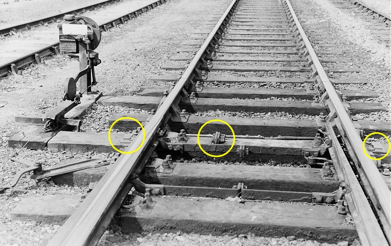
Close-up pic, marked to show the set in the turnout-side stock rail:

Thanks to Mick Nicholson for the pics.
regards,
Martin.
40+ years developing Templot. Enjoy using Templot? Join Templot Club. Be a Templot supporter.
-
ginger61
- Posts: 35
- Joined: Wed Jan 30, 2013 4:00 pm
Re: Building my first p4 points
Hi all,
Many thanks for the replies and the general "pointers" ( sorry pun not intended!!). I hadn't even thought about the sole plate so will look into that in more detail!!!! Going back to the original topic, I take it that you put the extra parts on top of a slide chair to build it up properly? As i said earlier this is a first attempt at a p4 point as i have cut a few corners with the slightly narrower gauge and tried to add them in after the points were built( now realised that it's not a good idea!!!)
Martin, How do you advise making the set in the stock rails?
Once again many thanks for the answers to a tricky situation and i'll try and remember how to put pictures( or ask eldest daughter to show me the way!!!!)
Nick.
-
Martin Wynne
- Posts: 1172
- Joined: Mon May 14, 2012 4:27 pm
Re: Building my first p4 points
ginger61 wrote:Martin, How do you advise making the set in the stock rails?
Hi Nick,
Here's a simple idea which costs nothing and is a good way to make precise symmetrical bends in bullhead rail. It needs a bit of practice to know how hard to tap!
Hopefully the diagram is self-explanatory. Just two bits of rail about an inch long laid side by side with a gap between. The smaller the gap, so the harder you need to hit, but the more precisely located will be the bend. Make sure the stock rail is exactly square across them before making the bend -- a sheet of graph paper underneath helps with this.

For some notes on making the set and fixing the rail, see: http://85a.co.uk/forum/view_topic.php?id=491&forum_id=1
regards,
Martin.
40+ years developing Templot. Enjoy using Templot? Join Templot Club. Be a Templot supporter.
-
steve howe

- Posts: 912
- Joined: Sun Feb 01, 2009 10:16 pm
Re: Building my first p4 points
Here's a simple idea which costs nothing and is a good way to make precise symmetrical bends in bullhead rail. It needs a bit of practice to know how hard to tap
Must give that a try...I'm in the habit of putting a fine piercing saw cut across the rail just to the depth of the head and foot on the inside of the bend in the hope of getting a nice sharp bend in knuckle rails but I believe this is frowned upon in certain quarters
Steve
-
steve howe
- Posts: 912
- Joined: Sun Feb 01, 2009 10:16 pm
Re: Building my first p4 points
I'm not sure if this also appears on this forum, but it raised a lot of interest on RMWeb as an easy way to make crossing vees.
http://www.rmweb.co.uk/community/index. ... page-2?hl= crossing vee
I didn't believe it either so gave it a try and it works beautifully
steve
http://www.rmweb.co.uk/community/index. ... page-2?hl= crossing vee
I didn't believe it either so gave it a try and it works beautifully
steve
-
Terry Bendall
- Forum Team
- Posts: 2428
- Joined: Sun Jul 27, 2008 7:46 am
Re: Building my first p4 points
Martin Wynne wrote:Modelling them is tricky because the timber must be dropped below the level of the rest to accommodate the thickness of the sole plate underneath the chairs.
In the kits sold by Colin Criag, this problem is avoided by the use of etched bases for the slide chairs, which have cast pewter cosmetic rail fixing added later. Colin's kits use copper clad sleepers with the rail spaced away from them with an etched spacer. The sole plate is in two parts and this is solderd to the relevant sleeper with a piece of paper in between to give the insulation. The sleeper is also gapped to ensure insulation. He than supplies two special thin slide chair bases which fit on top of the sole plate. This avoids having to reduce the thickness of the sleeper.
I described the construction of Colin's flat bottom track and turnouts in No 174 of the News and those who attend Scaleforum will see the end product in use on Elcot Road. Colin will also be there.
steve howe wrote:I'm not sure if this also appears on this forum, but it raised a lot of interest on RMWeb as an easy way to make crossing vees
This looked very good. An excellent example of Brian's approach. I shall certainly try it when i next have to make some vees.
Terry Bendall
-
Martin Wynne
- Posts: 1172
- Joined: Mon May 14, 2012 4:27 pm
Re: Building my first p4 points
Terry Bendall wrote:He than supplies two special thin slide chair bases which fit on top of the sole plate. This avoids having to reduce the thickness of the sleeper.
Hi Terry,
That solves the modelling problem but it's not prototypical -- the prototype doesn't use special thin-based slide chairs/baseplates on soleplates. Having gone to so much trouble to model prototypical pointwork correctly, that seems rather a shame.
regards,
Martin.
40+ years developing Templot. Enjoy using Templot? Join Templot Club. Be a Templot supporter.
-
LesGros

- Posts: 546
- Joined: Thu Oct 08, 2009 10:05 pm
Re: Building my first p4 points
Martin Wynne wrote:
 Would it not be possible to build the bulk of the turnout using Exacto "thick" sleepers and mounting the slide chairs with plate on C&L "thins"?
In the photo showing the "set", it appears that the slide chairs are recessed into the sleeper; therefore, it should be possible to model using the Exacto thick sleepers.
...Modelling them is tricky because the timber must be dropped below the level of the rest to accommodate the thickness of the sole plate underneath the chairs. That's not a problem on the prototype but it is awkward to model. It means either using a thinner (and weaker) timber, or having a slot in the paper template and a recess in the work-board during construction. And a similar recess in the foam or cork roadbed on the layout.
The soleplate usually has some means to prevent gauge-spread movement of the chairs. Sometimes the end of the plate is simply turned up against the edge of the chair, or in this case on an LNER switch small blocks have been welded to the ends of the sole plate to restrain the chairs. Notice also that if a track circuit is present, the soleplate must be split in two and insulated in the middle... :
In the photo showing the "set", it appears that the slide chairs are recessed into the sleeper; therefore, it should be possible to model using the Exacto thick sleepers.
LesG
The man who never made a mistake
never made anything useful
The man who never made a mistake
never made anything useful
-
Terry Bendall
- Forum Team
- Posts: 2428
- Joined: Sun Jul 27, 2008 7:46 am
Re: Building my first p4 points
Martin Wynne wrote:That solves the modelling problem but it's not prototypical -- the prototype doesn't use special thin-based slide chairs/baseplates on soleplates
I agree Martin. The difference is 10 thou so probably most people would not notice.
Terry Bendall
-
ginger61
- Posts: 35
- Joined: Wed Jan 30, 2013 4:00 pm
Re: Building my first p4 points
Hi all,
Sorry for not replying sooner, but many thanks for all the replies. The next question is concerning the switch blades. Where do you "hinge" them and what method do people use? I'm still in the feeding chairs onto rails and making sure that i get it "right".
Many thanks in advance,
Nick.
Sorry for not replying sooner, but many thanks for all the replies. The next question is concerning the switch blades. Where do you "hinge" them and what method do people use? I'm still in the feeding chairs onto rails and making sure that i get it "right".
Many thanks in advance,
Nick.
-
mikeg
Re: Building my first p4 points
Nick - if it helps I will bring along my first attempt at pointbuilding to our NEEAG meeting on Thursday. It may help to clarify some issues. There are certainly enough skilled members at our meetings to help you (and me!) out.
Return to “Track and Turnouts”
Who is online
Users browsing this forum: YandexBot and 0 guests